Novel capillary structure configuration structure of soaking plate

A vapor chamber and capillary technology, applied in the field of innovative design of capillary configuration structure, can solve the problems of efficiency and quality impact, multiple costs and man-hours, and the difficulty of further improving heat conduction benefits, so as to improve heat conduction benefits and reduce manufacturing costs Effect

Inactive Publication Date: 2016-10-26
SUZHOU FORCECON ELECTRIC
View PDF3 Cites 1 Cited by
  • Summary
  • Abstract
  • Description
  • Claims
  • Application Information

AI Technical Summary

Problems solved by technology

[0005] However, in the course of the follow-up continuous research and development testing, the inventor found that there are still some problems and deficiencies in the structural design of the previous proposal. Mainly, in this way, the heat temperature of the vapor chamber after being heated is still concentrated in the middle area and it is difficult to spread evenly to the periphery, resulting in the disadvantage that it is difficult to further improve the heat conduction benefit; on the other hand, the capillary shown in the previous case The organization is a morphological design composed of multiple unit capillary structures. The number of groups of capillary structures in the previous proposal must reach a certain number to achieve the required heat conduction efficiency. However, too many capillary structures are located on the upper, During the sealing and vacuuming process of the lower casing, the fixing of its position will become a difficult problem in implementation. It will cost more cost and man-hours to make it fixed, and if it is not fixed, once the capillary tissue deviates from the originally designed position, even if it does not necessarily lose its function, it will definitely affect the due performance and quality

Method used


Image

  • Novel capillary structure configuration structure of soaking plate
  • Novel capillary structure configuration structure of soaking plate
  • Novel capillary structure configuration structure of soaking plate

Examples


Embodiment

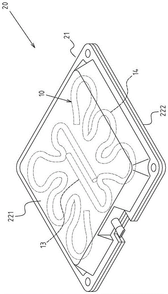
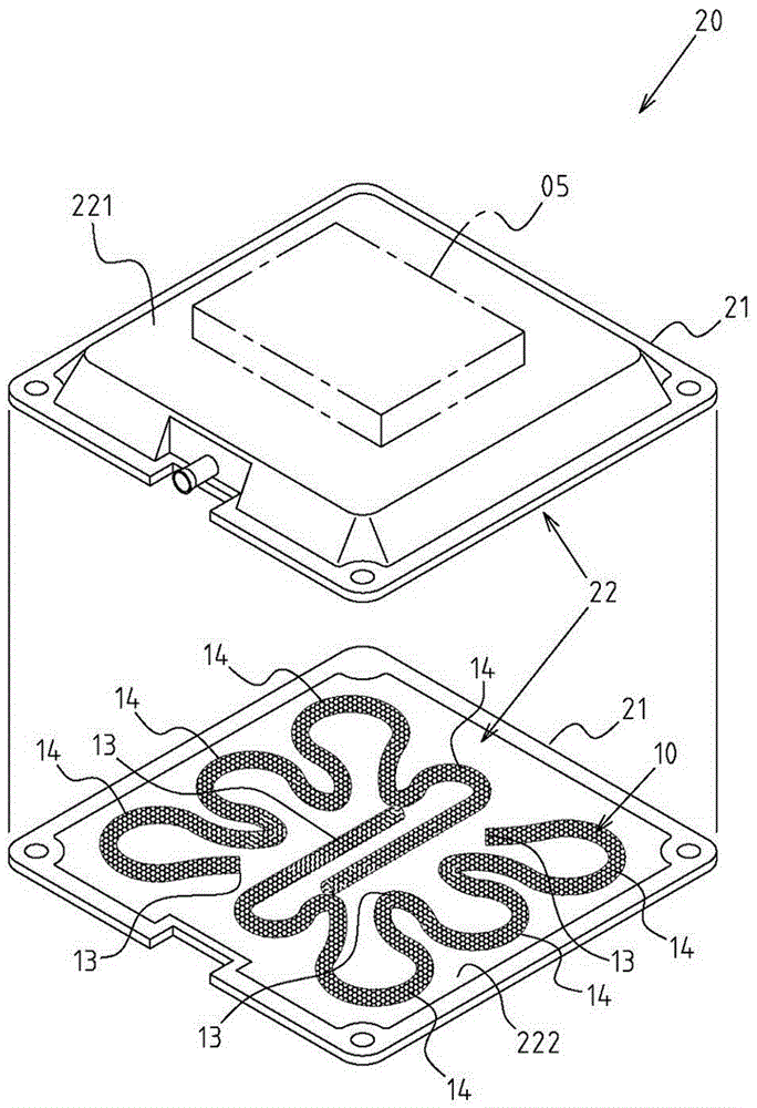
[0027] Example: see Figure 1~4 As shown, it is a preferred embodiment of the new capillary configuration structure and configuration method of the vapor chamber of the present invention, but these embodiments are only for illustration purposes, and are not limited by this structure in patent applications;

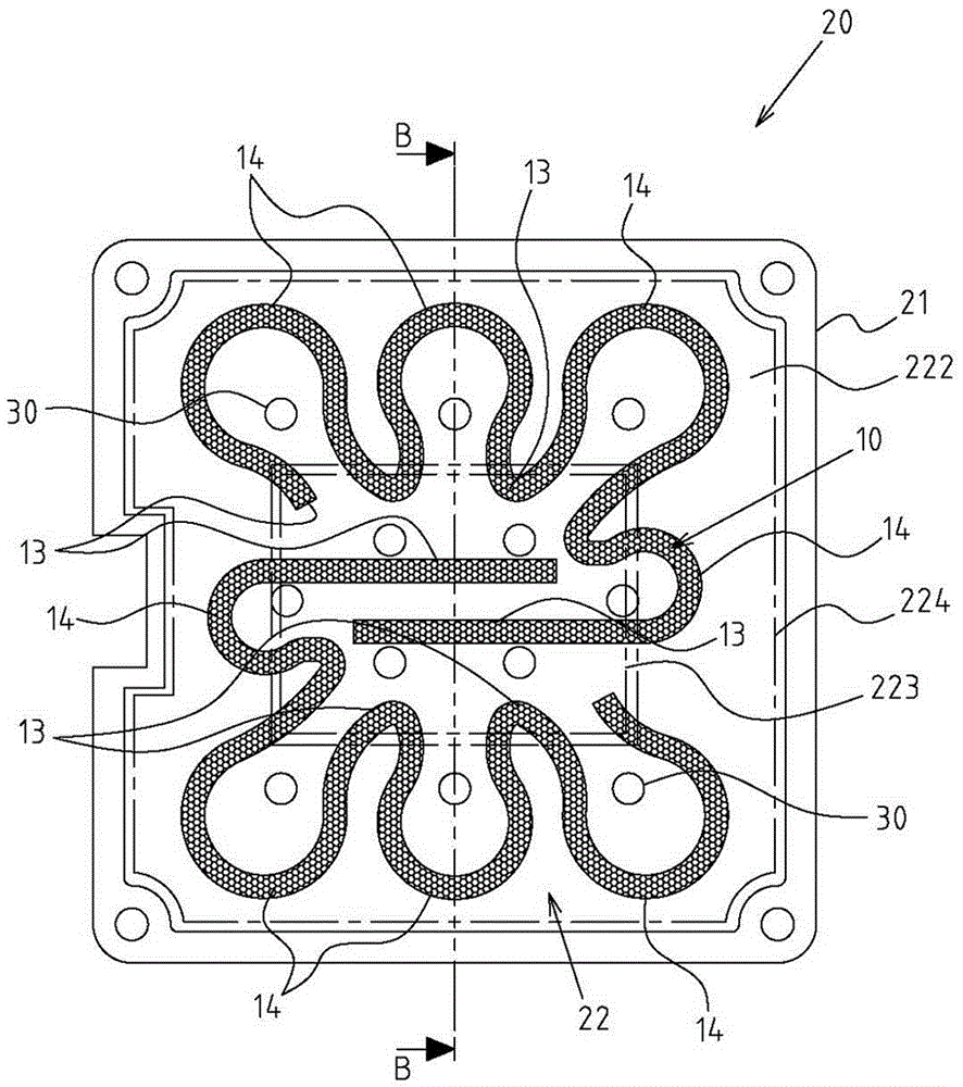
[0028] The capillary tissue 10 is arranged in a hollow chamber 22 provided in the housing 21 of a vapor chamber 20, and the first side 11 of the capillary tissue 10 is in contact with the top wall 221 of the hollow chamber 22, the The second side 12 of the capillary tissue 10 is then in contact with the bottom wall 222 of the hollow chamber 22; image 3 As shown, the hollow chamber 22 includes a central region 223 and a peripheral region 224 adjacent to the periphery of the vapor chamber 20; and wherein:

[0029] The capillary tissue 10 is set in a continuously curved and extended form, and the extended distribution range of the capillary tissue 10 covers the central area...


PUM


Abstract

The invention discloses a novel capillary structure configuration structure of a soaking plate. A capillary structure is arranged in a hollow groove formed in a shell of the soaking plate; a first side of the capillary structure is contacted with the top wall of the hollow groove; a second side of the capillary structure is contacted with the bottom wall of the hollow groove; and the hollow groove includes a center area and a peripheral area near the periphery of the soaking plate. The novel capillary structure configuration structure is mainly characterized in that the capillary structure is set as a continuous bend extending shape; and the extending distribution range of the capillary structure covers the center area and the peripheral area of the hollow groove, so that a structural form of the capillary structure including a center heat conducting part corresponding to the center area and a peripheral cooling part corresponding to the peripheral area is formed, and the better industrial economic benefits of greatly improving the heat transfer benefit and the practical advancement of the quality of the soaking plate and reducing the manufacturing cost can be achieved.

Description

technical field [0001] The invention relates to a vapor chamber, in particular to an innovative design of the capillary configuration structure of the vapor chamber. Background technique [0002] The vapor chamber referred to in the present invention is widely used as a heat dissipation guide structure, for example, as a computer CPU heat dissipation component. [0003] As for the existing structure of the vapor chamber, it generally has a flat shell, and a hollow chamber is formed inside the shell, and capillary tissue (such as sintered body, mesh body, etc.) is covered on the peripheral wall of the hollow chamber to improve In order to prevent the expansion of the hollow chamber when heated and cause the arc deformation of the top and bottom walls of the shell, there is an industry that adds a coupling column (or a slat-shaped member) between the top and bottom walls of the shell. But this kind of existing structure is still found in practical application, the heat source...

Claims


Application Information

Patent Timeline
Patent Type & Authority Applications(China)
IPC IPC(8): F28D15/04
CPCF28D15/046
Inventor 何信威陈彦辰
Owner SUZHOU FORCECON ELECTRIC
Why Eureka
Try Eureka