
Multi-channel power grid voltage synchronous signal extraction device and method

A technology of grid voltage and synchronization signal, applied in the field of signal processing, can solve the problems such as the increase of calculation amount and the complexity of system structure, the inability to extract synchronization signals, and the inability to provide multi-frequency positive and negative sequence signals, etc.

Inactive Publication Date: 2016-10-26
CHONGQING UNIV
View PDF5 Cites 7 Cited by
  • Summary
  • Abstract
  • Description
  • Claims
  • Application Information

AI Technical Summary

Problems solved by technology

This structure can effectively filter the influence of grid voltage asymmetry on synchronous signal extraction, but the operation of instantaneous symmetric components increases the computational complexity of the system and the complexity of the system structure
[0009] Therefore, the existing power grid voltage synchronization signal extraction devices are mainly aimed at the fundamental wave signal extraction of the power grid, and cannot provide multi-frequency positive and negative sequence signals, nor can they quickly and accurately extract synchronization signals under the condition of grid voltage asymmetry. Due to the requirements of frequency adaptability and simplicity of implementation, a new grid voltage synchronization signal extraction technology is urgently needed to overcome the above defects

Method used


Image

  • Multi-channel power grid voltage synchronous signal extraction device and method
  • Multi-channel power grid voltage synchronous signal extraction device and method
  • Multi-channel power grid voltage synchronous signal extraction device and method

Examples


Embodiment Construction

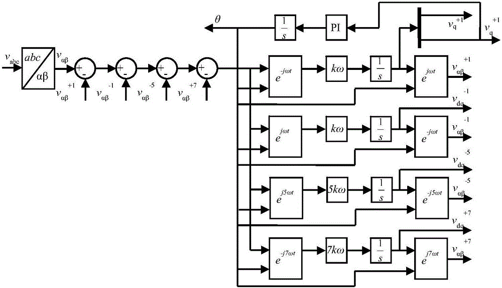
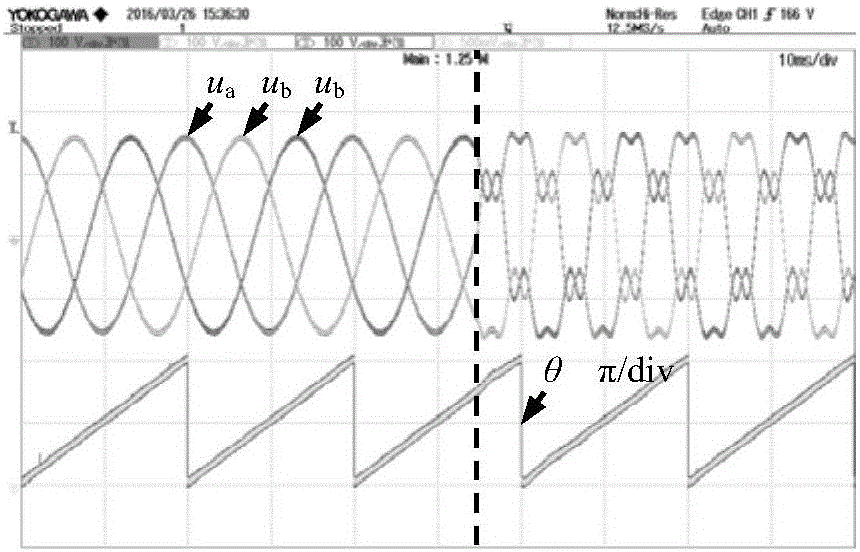
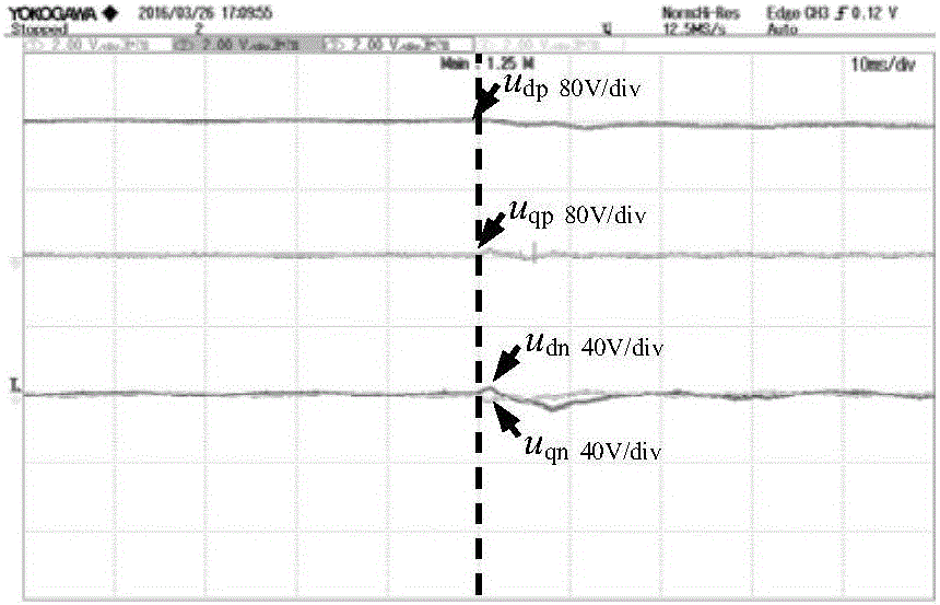
[0056] The present invention will be further described below in conjunction with accompanying drawing and embodiment: figure 1 It is a schematic structural view of the present invention; Fig. 2 is a waveform diagram of a voltage fundamental wave signal in each coordinate system when a harmonic mutation occurs in the input voltage; Figure 2a It is the waveform diagram of the input voltage and phase angle when the input voltage has a harmonic mutation; Figure 2b is the waveform diagram of the voltage fundamental wave signal in the dq coordinate system when the input voltage has a harmonic mutation; Figure 2c It is the waveform diagram of the voltage fundamental wave signal in the αβ coordinate system when the input voltage has a harmonic mutation; Fig. 3 is the waveform diagram of the voltage fundamental wave signal in each coordinate system when the input voltage with harmonics has an asymmetric mutation; Figure 3a It is the waveform diagram of the input voltage and phase ...


PUM


Abstract

The invention provides a multi-channel power grid voltage synchronous signal extraction device. The device comprises an [alpha]-[beta] stationary coordinate system transformation circuit T[alpha][beta], positive and negative sequence d-q synchronous rotating coordinate system transformation circuit e<j[omega]t>, e<-j[omega]t>, e<j5[omega]t> and e<-j7[omega]t> of different frequencies, a subtracter, a PI adjuster, an integrator and a proportion arithmetic unit. The multi-channel power grid voltage synchronous signal extraction device has the advantages that under the condition that an input voltage has different-frequency harmonic waves, the device is capable of extracting synchronous signals of fundamental waves and can also extracting different-frequency positive and negative sequence components under the [alpha]-[beta] coordinate system and the d-q coordinate system, and frequency adaptivity is realized; in addition, negative sequence decoupling or instant symmetric component separation is not needed, only a d-q synchronous rotating coordinate system transformation circuit Tdq and feedback are needed, the separation and extraction of fundamental wave positive and negative sequence components are realized under a single synchronous reference coordinate system, the structure is simpler, and the operation amount is smaller.

Description

technical field [0001] The invention relates to the field of signal processing, in particular to a multi-channel grid voltage synchronous signal extraction device and method. Background technique [0002] A converter is an electrical device that changes the voltage, frequency, number of phases, and other power or characteristics of the power system. There are many types of converters, which are widely used in various working machines. Among them, for three-phase grid-connected converters The most important step in inverter control is to extract the synchronous signal of the grid voltage, that is, the amplitude, phase and frequency of the fundamental wave and each harmonic voltage. Since grid voltage asymmetry is a common phenomenon, it has a great impact on the operation of the three-phase grid-connected converter; therefore, in order to meet the needs of the asymmetric control strategy of the three-phase grid-connected converter, the synchronous signal The extraction also ...

Claims


Application Information

Patent Timeline
IPC IPC(8): G01R19/00
CPCG01R19/0084
Inventor 杜雄顾师达王国宁杨友耕熊浩邹小明时颖孙鹏菊周雒维
Owner CHONGQING UNIV
Learn More