Distributed passive radar target detection realization method

A passive radar, target detection technology, applied in radio wave measurement systems, radio wave reflection/re-radiation, measurement devices, etc., can solve the problem of multi-step iterative processing and time-consuming, improve target detection probability, save positioning Time and effect of stable target detection performance

Active Publication Date: 2016-10-26
NAVAL AVIATION UNIV
View PDF4 Cites 9 Cited by
  • Summary
  • Abstract
  • Description
  • Claims
  • Application Information

AI Technical Summary

Problems solved by technology

The biggest defect of this traditional processing method is that the multi-step iterative processing takes a long time, and the positioning ambiguity problem in the positioning process is the target "ghost point", which requires complex "ghost point" logic, which can be eliminated through subsequent further processing. remove
In practical application, due to the influence of complex terrain environment on the deployment of multiple receivers, there is a positioning ambiguity problem that is difficult to solve between different receiver arrays

Method used


Image

  • Distributed passive radar target detection realization method
  • Distributed passive radar target detection realization method
  • Distributed passive radar target detection realization method

Examples


Embodiment Construction

[0025] The present invention will be described in further detail below in conjunction with the accompanying drawings.

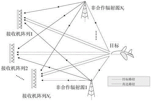
[0026] Such as figure 1 As shown, the distributed passive radar system includes N t transmitters, which are also called non-cooperative radiation sources in the field of passive radar, N r receiver array, 1 target, where N t ≥2,N r ≥2.

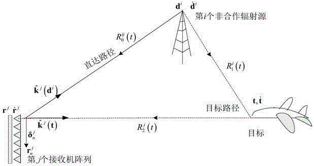
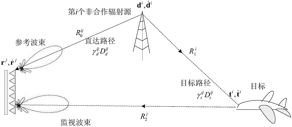
[0027] Such as figure 2 As shown, the ij-th transmitter-target-receiver pair in the distributed passive radar system is also called the ij-th bistatic pair, and the position and velocity of the i-th transmitter are denoted as d i and i=1,...,N t , the position and velocity of the jth receiver array are denoted as r j and j=1,...,N r , while the position and velocity of the target are denoted as t and where d i , r j , t, are all functions of time. In general, the transmitter and receiver, and the target are moving. The distance from the i-th transmitter to the j-th receiver is Similarly, and rep...


PUM


Abstract

The invention discloses a distributed passive radar target detection realization method, and the method belongs to the technical field of passive radar target detection. An existing target detection method is characterized by carrying out correlation and over-threshold processing independently on each bistatic pair to finish target detection, and then, obtaining bistatic distance and Doppler information of a target through estimation and carrying out target location, which results in the problem of complex ambiguous location needing to be solved in the follow-up target exact positioning process. In order to solve the problem above, the invention introduces target location and velocity vector and constructs centralized target detection statistics, so that target positioning is realized while realizing target detection, and the problem of ambiguous target location no longer needs to be treated. Besides, the method carries out non-phase-coherent accumulation on a plurality of transmitter-receiver pairs before detection to obtain space diversity gains, thereby improving target detection probability, obtaining more-stable target detection performance and providing basis for continuous and stable tracking of the target.

Description

technical field [0001] The invention belongs to the technical field of passive radar target detection, in particular to a method for realizing distributed passive radar target detection. Background technique [0002] The passive radar system uses signals emitted by third-party radiation sources, such as FM radio, DAB, DVB-T, GPS signals, and signals emitted by various mobile communication base stations, to irradiate the target to realize the detection of small air targets and low-altitude flying targets And positioning, so it is also called external radiation source radar. The object detection and localization performance of passive radar systems has been steadily improving over the past decade. However, from the perspective of the system system, the passive radar systems disclosed in recent years are mainly based on the bistatic geometric structure of single launch and single reception, and the target detection performance is greatly affected by the geometric position and ...

Claims


Application Information

Patent Timeline
Patent Type & Authority Applications(China)
IPC IPC(8): G01S13/04
CPCG01S13/04
Inventor 张财生朱洪伟唐小明刘明春李国君张涛宋洪良
Owner NAVAL AVIATION UNIV
Why Eureka
Try Eureka