Safety monitoring method, device, system and monitoring system
A technology for safety monitoring and environmental monitoring, which can be used in CCTV systems, televisions, instruments, etc., and can solve problems such as monitoring blind spots.
- Summary
- Abstract
- Description
- Claims
- Application Information
AI Technical Summary
Problems solved by technology
Method used
Image

Examples
Embodiment 1
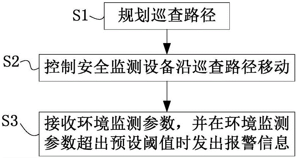
[0055] This embodiment provides a safety monitoring method, such as figure 1 shown, including:
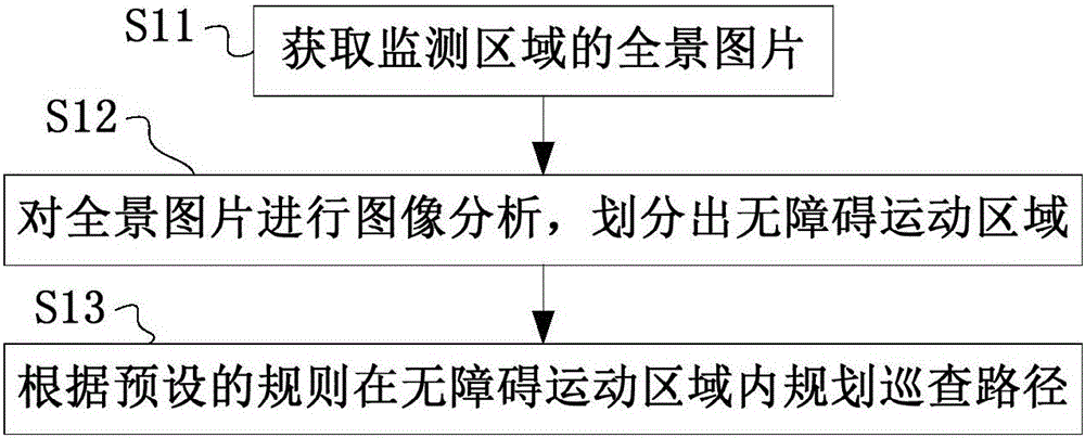
[0056]S1. Plan the inspection route.
[0057] S2. Control the safety monitoring equipment to move along the inspection path. Specifically, the safety monitoring device can be a device including a control chip and a motion actuator controlled by the control chip, such as an unmanned aerial vehicle, an automatic control car, etc., and an application program capable of executing the safety monitoring method in this embodiment is entered in the control chip, The movement actuator is controlled by the control chip to adjust the movement path of the safety monitoring equipment, so that the safety monitoring equipment can move along the inspection path, and patrol and monitor the monitoring area.
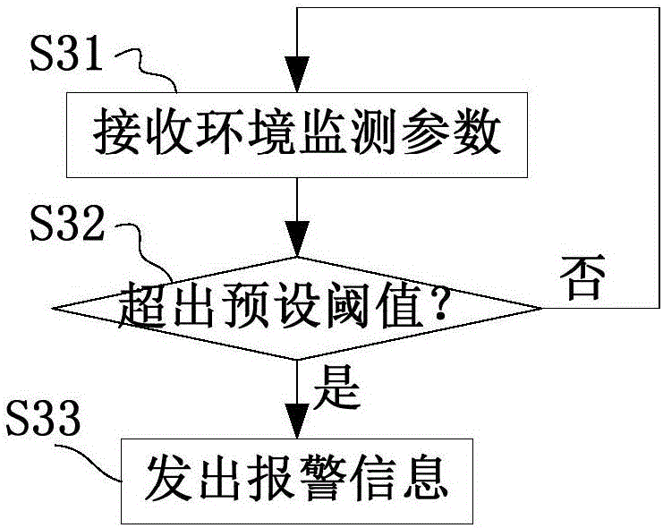
[0058] S3. Receive the environmental monitoring parameters collected during the movement of the security monitoring equipment, and send an alarm message when the environmental monitoring para...
Embodiment 2
[0080] This embodiment provides a safety monitoring device, such as Figure 5 As shown, the safety monitoring device 1 includes:
[0081] The path planning unit 11 is used for planning the inspection path.
[0082] The control unit 12 is used to control the safety monitoring equipment to move along the inspection path.
[0083] The monitoring unit 13 is configured to receive environmental monitoring parameters collected during the movement of the safety monitoring equipment, and send an alarm message when the environmental monitoring parameters exceed a preset threshold.
[0084] The safety monitoring device 1 in this embodiment first plans the inspection path of the monitoring area through the path planning unit 11, and then controls the safety monitoring equipment to move along the inspection path through the control unit 12, and receives the information during the movement of the safety monitoring equipment through the monitoring unit 13. The collected environmental monit...
Embodiment 3
[0097] This embodiment provides a safety monitoring system, such as Figure 6 As shown, the safety monitoring device 1 and the safety monitoring device 2 in the second embodiment are included, and the safety monitoring device 2 includes a camera device 21 , an environment monitoring parameter acquisition device 22 and a motion execution device 23 .
[0098] The camera device 21 is used to collect images and transmit them to the safety monitoring device 1 . Specifically, when the safety monitoring device 2 is an automatic control car, the camera 21 can be installed on the head or top of the automatic control car for upward shooting; when the safety monitoring device 2 is an unmanned aerial vehicle, the camera 21 can be installed on the An overhead shot of the bottom of the man-machine.
[0099] The environment monitoring parameter collection device 22 is used to collect the safety monitoring parameters of the environment where the safety monitoring device 2 is located and tran...
PUM
 Abstract
Description
Claims
Application Information
 - R&D
- Intellectual Property
- Life Sciences
- Materials
- Tech Scout
- Unparalleled Data Quality
- Higher Quality Content
- 60% Fewer Hallucinations
Browse by: Latest US Patents, China's latest patents, Technical Efficacy Thesaurus, Application Domain, Technology Topic, Popular Technical Reports.
© 2025 PatSnap. All rights reserved.Legal|Privacy policy|Modern Slavery Act Transparency Statement|Sitemap|About US| Contact US: help@patsnap.com