Surface-mounted magnetic element and production technology thereof

A magnetic component, surface mount technology, applied in the direction of electrical components, transformer/inductor parts, transformer/reactor installation/support/suspension, etc. Difficult automatic machine realization and other issues, to achieve the effect of high consistency, low production cost, and low material cost

Active Publication Date: 2016-10-26
珠海科德电子有限公司
View PDF5 Cites 0 Cited by
  • Summary
  • Abstract
  • Description
  • Claims
  • Application Information

AI Technical Summary

Problems solved by technology

The former method is more suitable for vertical magnetic components, but the vertical components are often inconsistent with the flattening direction of the product; the latter method is mostly used on horizontal magnetic components, and the independent fastener assembly operation is more difficult for automatic machines.
[0004] Magnetic cores and coils are the necessary core materials for magnetic compone

Method used


Image

  • Surface-mounted magnetic element and production technology thereof
  • Surface-mounted magnetic element and production technology thereof

Examples


Embodiment 1

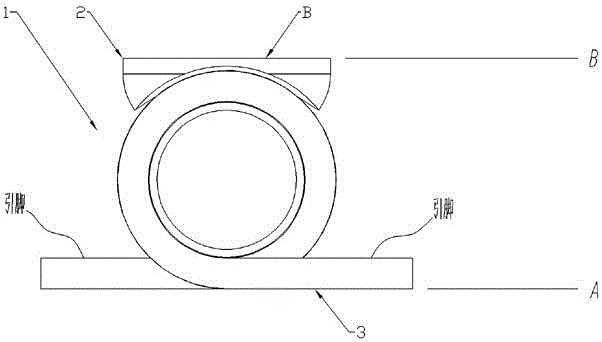
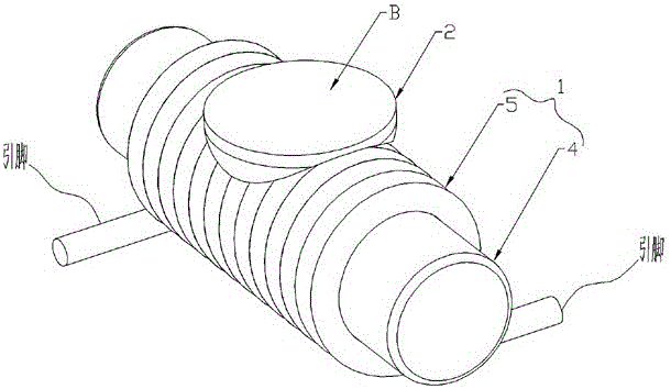
[0023] like figure 1 and figure 2 As shown, in this embodiment, the surface mount magnetic component includes a magnetic component main body 1 and a glue part 2 adhered to the magnetic component main body 1, and all pins of the magnetic component main body 1 The bottom 3 is located on the same horizontal plane A, and the top of the glue part 2 is provided with an adsorption plane B, and the adsorption plane B and the horizontal plane A are parallel to each other.

[0024] In this embodiment, the magnetic element main body 1 includes a magnetic core 4 and a coil 5 wound on the magnetic core 4 , and the glue part 2 is adhered to the coil 5 .

[0025] In this embodiment, the glue part 2 is located above the middle part of the coil 5 .

[0026] In this embodiment, the production process of the surface mount magnetic component includes the following steps:

[0027] a. Set the bottoms 3 of all the pins of the magnetic element body 1 on the same horizontal plane A, and place the ...

Embodiment 2

[0033] In this embodiment, the production process of the surface mount magnetic component includes the following steps:

[0034] a. Set the bottoms 3 of all the pins of the magnetic element body 1 on the same horizontal plane A, and place the magnetic element body 1 on the working plane, and the bottoms 3 of all the pins of the magnetic element body 1 are supported on on said working plane;

[0035] b. Dropping colloidal material on the magnetic element main body 1, so that the colloidal material forms a convex portion on the magnetic element main body 1;

[0036] c. Turn the magnetic element main body 1 over 180°, and then press the top of the colloidal material on the flat plate, so that the top of the colloidal material forms an adsorption plane B, which is parallel to the magnetic The level A in which the bottoms 3 of all pins of the component body 1 lie.

[0037] In this embodiment, the flat plate is a light-transmitting plate, and an ultraviolet light source is arrange...


PUM


Abstract

The invention discloses a surface-mounted magnetic element and a production technology thereof, and aims to provide the surface-mounted magnetic element which is simple in structure, low in material cost and good in consistency and can be matched with mechanical equipment to realize automatic production and also provide the production technology of the surface-mounted magnetic element is low in cost, good in consistency, high in reliability and simple in technology. The surface-mounted magnetic element comprises a magnetic element main body (1) and a glue part (2) adhered onto the magnetic element main body (1), wherein the bottoms (3) of all pins of the magnetic element main body (1) are positioned on a same horizontal plane (A); an adsorption plane (B) is arranged on the top of the glue part (2); and the adsorption plane (B) and the horizontal plane (A) are parallel to each other. The production technology of the surface-mounted magnetic element comprises leveling, glue coating, surface manufacturing and the like. The production technology can be applied to the technical field of surface-mounted magnetic elements.

Description

technical field [0001] The invention relates to a surface-mounted magnetic element applied to electronic and electrical products, and also relates to a production process of the surface-mounted magnetic element. Background technique [0002] With the improvement of people's living standards, the requirements for cost performance and miniaturization of electronic and electrical products are getting higher and higher, and the real electronic products are promoted to develop in the direction of high reliability and full automation. In order to meet international standards and industry standards for The reliability requirements of electronic products, especially in the field of automotive electronics applications, all involved products must pass various environmental and mechanical reliability tests. In order to ensure the life of the products in the application, the assembly process should avoid Product consistency defects are caused by "people" problems; in order to reduce cos...

Claims


Application Information

Patent Timeline
IPC IPC(8): H01F27/06
CPCH01F27/027H01F27/06
Inventor 李成军
Owner 珠海科德电子有限公司
Why Eureka
Try Eureka