Transformer pulling board

A technology for transformers and pulling plates, which is applied to transformer/inductor parts, transformer/inductor coils/windings/connections, electrical components, etc. effect of dosage

Inactive Publication Date: 2016-10-26
CEEG JIANGSU
View PDF6 Cites 1 Cited by
  • Summary
  • Abstract
  • Description
  • Claims
  • Application Information

AI Technical Summary

Problems solved by technology

This connection structure has the following disadvantages: When installing the coil, first remove the upper clamp and the upper iron yoke of the iron core, and then install the coil, because the pull plate pin occupies the installation distance of the coil, so it is difficult to install the low-voltage coil

Method used


Image

  • Transformer pulling board
  • Transformer pulling board
  • Transformer pulling board

Examples


Embodiment 1

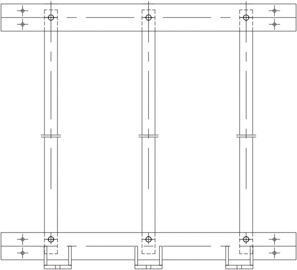
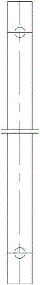
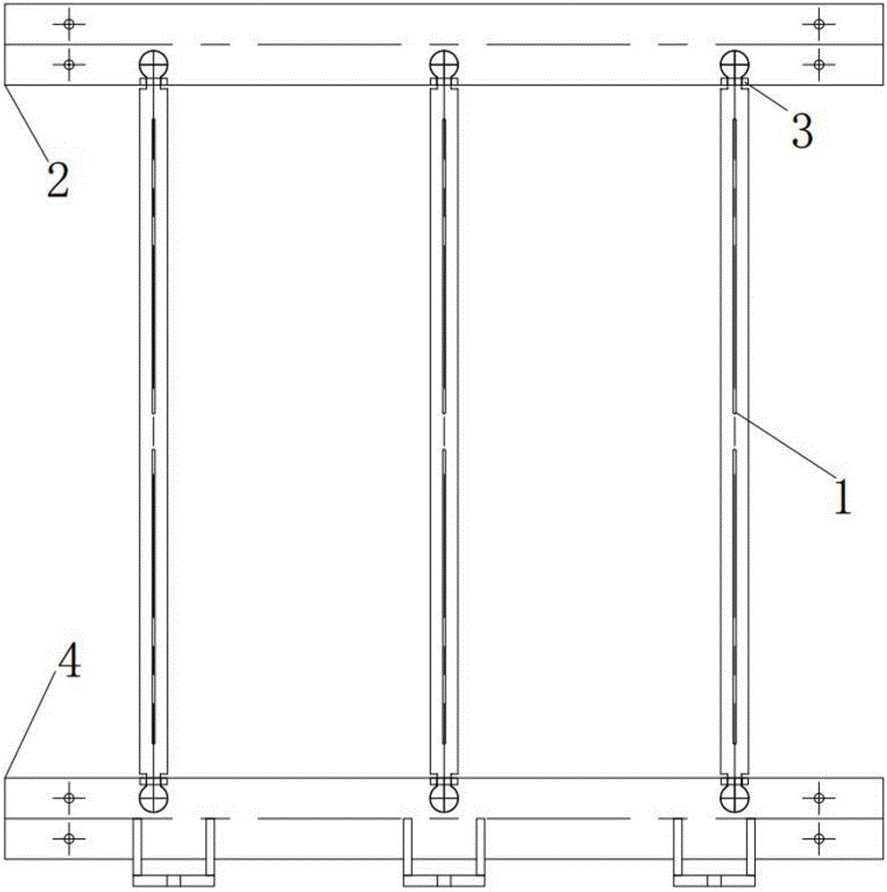
[0019] Such as Figure 3-5 Shown, a kind of transformer drawing board comprises drawing board (1), is divided into the clamping part of upper clamping part (2), lower clamping part (5) and the support plate (5) on the upper and lower clamping parts; ) are in the shape of an arc, and at the same time, the ends of the arc grooves of the upper clamp (2) and the lower clamp (4) are processed to match the corresponding size of the end of the pull plate, which can be embedded in the arc shape The upper clamp (2) and the lower clamp (4) cooperate with the pull plate (1), the pull plate (1) can be buckled with the upper and lower clamps, and the mating surface is flush, and the mating surface can bear The weight of the body during lifting; the support plate (3) welded to the end of the arc groove on the upper and lower clamps is used to prevent the outward arching deformation of the pull plate in the length direction and the displacement in the front and rear directions when the trans...


PUM


Abstract

The invention discloses a transformer pulling board which is characterized by comprising a pulling board (1), a clamping member and supporting boards (3) on the clamping member; the clamping member comprises an upper clamping member(2) and a lower clamping member (4); two ends of the pulling board (1) are arc-shaped; the end parts of the upper clamping member (2) and the lower clamping member (4) are provided with arc-shaped grooves which are matched and can be inserted in the arc-shaped structure. According to the transformer pulling board provided by the invention, the arc-shaped structure of the pulling board and the clamping member are connected in an embedded mode, and the arc-shape structure has a self-spacing function to restrict the displacement of the pulling board in vertical direction; the supporting boards welded on the upper clamping member and the lower clamping member are used in preventing the deformation of the pulling board and displacement of the pulling board in forwards and backwards direction during the lifting process of the transformer; The upper clamping member and the lower clamping member of the transformer pulling board are finally matched with the pulling board wherein the matched surface is leveled; at the same time, the pulling board and the clamping member are on one surface which reduces the consumption of transformer clamping member insulation; The transformer pulling board has simple processing technology and structure, and is convenient for assembly.

Description

technical field [0001] The invention relates to a transformer structure, in particular to a transformer pull plate. Background technique [0002] The existing transformer pull plate and clamp are connected by a pin shaft, that is, there is a through hole on the pull plate and the clamp, and the pin is welded in the two through holes on the pull plate and the bottom, and the through hole of the clamp passes through the pin and the iron core, The pull plates are connected together to form the skeleton of the transformer. This connection structure has the following disadvantages: when installing the coil, first remove the upper clamp and the upper iron yoke of the core, and then install the coil, because the pull plate pin occupies the installation distance of the coil, so it is difficult to install the low-voltage coil. Such as figure 1 and 2 Shown is an existing drawing plate structure of a dry-type transformer. Two holes are drilled at the upper and lower ends of the stee...

Claims


Application Information

Patent Timeline
IPC IPC(8): H01F27/30
CPCH01F27/306
Inventor 刘群
Owner CEEG JIANGSU
Why Eureka
Try Eureka