Solar electric vehicle charging controller

A solar electric vehicle and charging controller technology, which is applied in electric vehicle charging technology, electric vehicles, battery/fuel cell control devices, etc., can solve problems such as unfavorable waterproofing, waste of solar panel energy, energy waste, etc., and improve power generation utilization High efficiency, meet the outdoor use, meet the effect of high requirements

Active Publication Date: 2016-10-26
HEFEI SHANGSHUO NEW ENERGY
View PDF4 Cites 6 Cited by
  • Summary
  • Abstract
  • Description
  • Claims
  • Application Information

AI Technical Summary

Problems solved by technology

[0004] (1) Many solar electric vehicle controllers connect multiple battery panels in series to form a high open-circuit voltage to charge the battery. However, since the electric vehicle is in motion during normal use, part of the area of ​​the series-connected battery panels is easily shadowed Interference, because the panels are connected in series, the interference of one panel will affect the power generation efficiency of the entire solar panel and waste energy
[0005] (2) The existing solar electric vehicle charger connects the solar panels in series with a high voltage and directly uses a series MOS circuit structure to charge the battery, so that when the battery is charged, the voltage of the solar panel will be equal to the voltage of the battery , so that the solar panel deviates from the maximum power point, wasting the energy of the solar panel
Since the full voltage parameters of each type of battery are different, it is necessary to use each solar electric vehicle charger to charge only one of the lead-acid batteries corresponding to one of the voltage levels. It is extremely inconvenient to use dial switches or buttons to adjust. And not conducive to waterproof

Method used


Image

  • Solar electric vehicle charging controller
  • Solar electric vehicle charging controller
  • Solar electric vehicle charging controller

Examples


Embodiment Construction

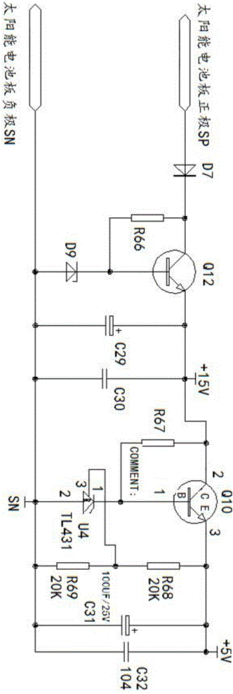
[0042] A solar electric vehicle charge controller, such as figure 2 As shown, it includes a housing 100 and a circuit board 101 installed in the housing. The circuit board 101 is provided with a control circuit, and the control circuit includes: an input module circuit 2, an input voltage sampling circuit 3, an input current sampling circuit 4, a Voltage main circuit 11 , MCU main control chip 7 , MCU peripheral circuit 6 , digital-to-analog conversion circuit 5 , pulse width modulator drive circuit 8 , output voltage sampling circuit 9 and output module circuit 12 .

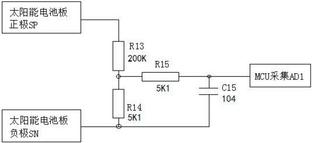
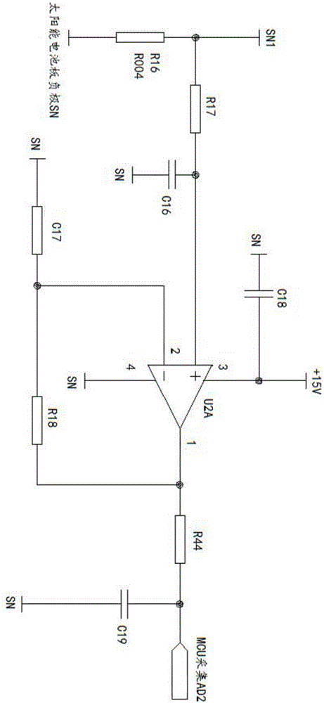
[0043] see figure 1 , the external solar panel 1 is connected to the external storage battery 10 through the sequentially connected input module circuit 2, booster main circuit 11 and output module circuit 12;

[0044]The nodes between the input module circuit 2 and the boost main circuit 11 are respectively connected to the MCU main control chip 7 through the input voltage sampling circuit 3 and the input cur...


PUM


Abstract

The invention discloses a solar electric vehicle charging controller. The solar electric vehicle charging controller comprises a shell and a circuit board installed in the shell; a control circuit is arranged on the circuit board; the control circuit comprises an input module circuit, an input voltage sampling circuit, an input current sampling circuit, a boosted main circuit, a MCU main control chip, a MCU peripheral circuit, a digital-analogue conversion circuit, a pulse width modulator driving circuit, an output voltage sampling circuit and an output module circuit. The charging controller provided by the invention can automatically identify the voltage grades of storage battery sets, and automatically output reasonable storage battery filling protection voltage according to different voltage grades of the storage battery sets; therefore, use operation of users is effectively simplified and convenient; simultaneously, the problem that a solar panel on an electric vehicle is easily interfered by a shadow can be avoided; the power generation efficiency of the solar cell panel is increased; waste of energy is avoided; and thus, the voltage of the storage battery can be acquired and identified when the storage battery is effectively filled fully and the output module circuit is closed.

Description

technical field [0001] The invention belongs to the technical field of off-grid solar energy storage and energy storage, and in particular relates to a charger for a solar electric tricycle and a sightseeing car, in particular to a charging controller for a solar electric vehicle. Background technique [0002] With the continuous development of solar charging technology, solar electric vehicles have gradually been widely used by people. The solar electric vehicle is based on the original electric vehicle, the roof of the electric vehicle is changed into a solar panel, and the battery is charged through a solar electric vehicle charger. The solar electric vehicle charger plays a key role as the core component. [0003] Problems with existing products: [0004] (1) Many solar electric vehicle controllers connect multiple battery panels in series to form a high open-circuit voltage to charge the battery. However, since the electric vehicle is in motion during normal use, part...

Claims


Application Information

Patent Timeline
Patent Type & Authority Applications(China)
IPC IPC(8): H02J7/00H02J7/35B60L11/18
CPCB60L58/10H02J7/0086H02J7/35Y02T10/70Y02T10/7072Y02T90/12
Inventor 杨益金李小罗
Owner HEFEI SHANGSHUO NEW ENERGY
Why Eureka
Try Eureka