Photovoltaic inverter auxiliary power supply and start-stop control method
A photovoltaic inverter and auxiliary power supply technology, applied in the photovoltaic field, can solve the problems of repeated starting and stopping, low load capacity, and reduced output voltage under the condition of insufficient light.
- Summary
- Abstract
- Description
- Claims
- Application Information
AI Technical Summary
Problems solved by technology
Method used
Image
Examples
Embodiment 1
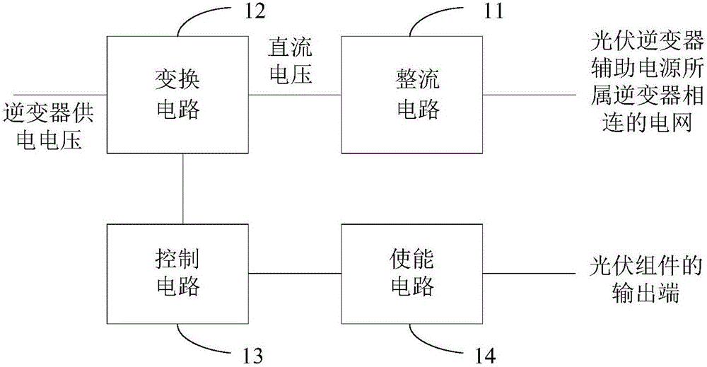
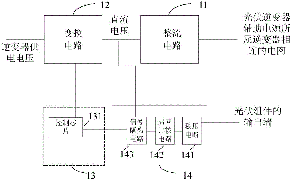
[0097] See figure 1 , which shows a schematic diagram of the logical structure of the photovoltaic inverter auxiliary power supply provided in this application. The photovoltaic inverter auxiliary power supply includes: a rectification circuit 11 , a conversion circuit 12 , a control circuit 13 and an enabling circuit 14 .
[0098] The input end of the rectification circuit 11 is connected to the grid connected to the inverter to which the auxiliary power supply of the photovoltaic inverter belongs, the output end of the rectification circuit 11 is connected to the first input end of the conversion circuit 12, and the conversion The output end of the circuit 12 is connected with each device in the inverter to which the auxiliary power supply of the photovoltaic inverter belongs.
[0099] The first input end of the enabling circuit 14 is connected to the output end of the photovoltaic module, the output end of the enabling circuit 14 is connected to the first input end of the c...
Embodiment 2
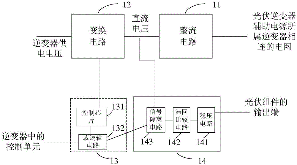
[0118] In this example, in figure 2 Another auxiliary power supply for photovoltaic inverters is extended on the basis of the auxiliary power supply for photovoltaic inverters shown, please refer to image 3 ,exist figure 2 On the basis of the photovoltaic inverter auxiliary power shown, the control circuit 13 further includes an OR logic circuit 132 .
[0119] The output terminal of the signal isolation circuit 143 is connected to the first input terminal of the OR logic circuit 132 , and the output terminal of the OR logic circuit 132 is connected to the input terminal of the control chip 131 .
[0120] The signal isolation circuit 143 is configured to output the high-level first enable signal or the low-level first enable signal to the first input terminal of the OR logic circuit 132 .
[0121] The second input end of the OR logic circuit 132 is used as the second input end of the control circuit 13, and is connected to the control unit in the inverter, and is used to r...
Embodiment 3
[0132] In this example, in image 3 Another auxiliary power supply for photovoltaic inverters is extended on the basis of the auxiliary power supply for photovoltaic inverters shown, please refer to Figure 4 ,exist image 3 On the basis of the auxiliary power supply of the photovoltaic inverter shown, the second input terminal of the voltage stabilizing circuit 141 is used as the second input terminal of the enabling circuit 14, and is connected to the control unit in the inverter for After receiving the shutdown signal output by the control unit after the conversion circuit 12 outputs the inverter power supply voltage to each device in the inverter, and after a preset time interval.
[0133] The voltage stabilizing circuit 141 is configured to cut off the power supply voltage of the voltage stabilizing circuit 141 , the hysteresis comparison circuit 142 and the signal isolation circuit 143 when receiving the shutdown signal.
[0134] The OR logic circuit 132 is configured ...
PUM
 Abstract
Description
Claims
Application Information
 - R&D
- Intellectual Property
- Life Sciences
- Materials
- Tech Scout
- Unparalleled Data Quality
- Higher Quality Content
- 60% Fewer Hallucinations
Browse by: Latest US Patents, China's latest patents, Technical Efficacy Thesaurus, Application Domain, Technology Topic, Popular Technical Reports.
© 2025 PatSnap. All rights reserved.Legal|Privacy policy|Modern Slavery Act Transparency Statement|Sitemap|About US| Contact US: help@patsnap.com


