
Path loss modeling method for transformer substation environment

A technology of path loss model and modeling method, applied in electrical components, transmission monitoring, transmission system, etc., to achieve the effect of reducing estimation error, ensuring standardization, and simple measurement

Inactive Publication Date: 2016-10-26
GLOBAL ENERGY INTERCONNECTION RES INST CO LTD +4
View PDF5 Cites 0 Cited by
  • Summary
  • Abstract
  • Description
  • Claims
  • Application Information

AI Technical Summary

Problems solved by technology

[0012] The calculation methods of these parameters have their own advantages, but none of them can be well matched with the measured data of the wireless channel.

Method used


Image

  • Path loss modeling method for transformer substation environment
  • Path loss modeling method for transformer substation environment
  • Path loss modeling method for transformer substation environment

Examples


Embodiment Construction

[0047] The path loss modeling method provided by the present invention will be further described in detail below in conjunction with the accompanying drawings.

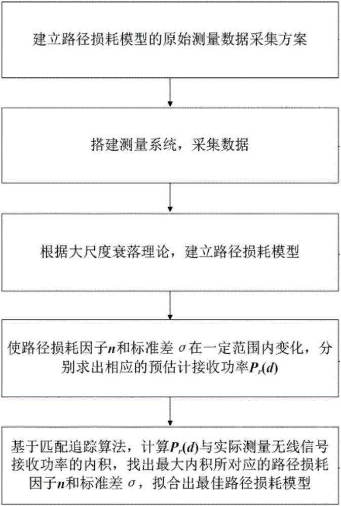
[0048] Such as figure 1 The overall scheme implementation flowchart of the present invention shown, in the modeling method of the path loss model provided by the present invention, comprise the following steps:

[0049] (1) Establish the original measurement data measurement scheme of the path loss model;

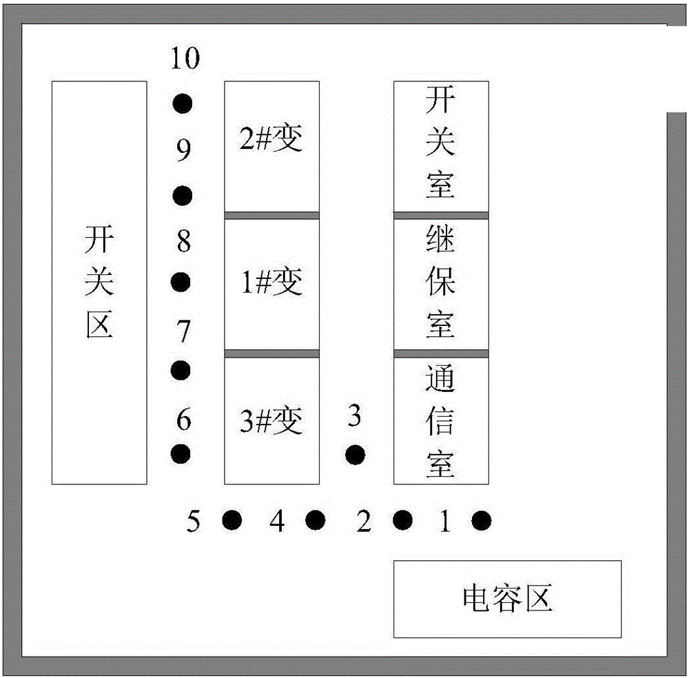
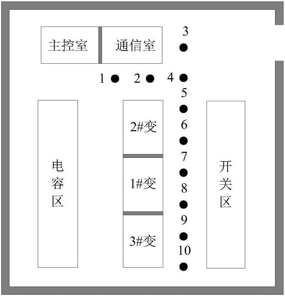
[0050] Such as figure 2 and image 3 As shown, they are the distribution diagrams of actually measuring the received power of wireless signals in 110kV and 220kV substations respectively. During the measurement process, the wireless signal source to be tested is placed in the communication room of the substation, and the position is fixed. The transmitting equipment consists of a signal source and a transmitting antenna. Composition, the signal source adopts AV1441A radio frequency signal generator, and the tra...


PUM


Abstract

The invention provides a path loss modeling method for a transformer substation environment. The method comprises the following steps of establishing a data measurement scheme, collecting data, establishing a path loss model and determining parameters of the path loss model. In the technical scheme provided by the invention, a large amount of sample data is not needed, the path loss property of a wireless signal in a transformer substation can be determined precisely and effectively, and the parameters obtained through computation can be better coincident to the measured data of a wireless channel.

Description

technical field [0001] The invention relates to the technical field of electric power wireless communication, in particular to a path loss modeling method for a substation environment. Background technique [0002] The smart grid, which uses power grids at all levels as the foundation of the grid, utilizes information and communication platforms established by various new technologies to realize comprehensive management of power transmission, power grid operation, and power business. As an important means of power information transmission, wireless communication has achieved fast and convenient communication, but it also faces many challenges. [0003] Taking the application environment of high-voltage substations as an example, since the electrical equipment of high-voltage substations will generate electromagnetic interference during operation, wireless communication equipment placed in substations with very harsh electromagnetic environments will be subject to different d...

Claims


Application Information

Patent Timeline
Patent Type & Authority Applications(China)
IPC IPC(8): H04B17/309H04B17/391
CPCH04B17/309H04B17/3911
Inventor 李强张洪欣陆阳李建岐吕英华刘伟麟安春燕张东磊刘文亮林树
Owner GLOBAL ENERGY INTERCONNECTION RES INST CO LTD
Learn More