A camera control device, a panoramic shooting method, and a mobile terminal
A panoramic shooting and control device technology, which is applied in the field of communication applications, can solve problems such as unevenness, picture dislocation, terminal shaking and rotation speed, etc., and achieve the effect of improving quality and preventing dislocation or stretching
- Summary
- Abstract
- Description
- Claims
- Application Information
AI Technical Summary
Problems solved by technology
Method used
Image
Examples
no. 1 example
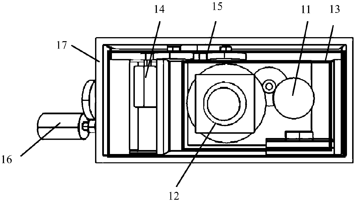
[0031] Embodiments of the present invention provide a camera control device, such as figure 1 shown, including:
[0032] The first driving structure 11, which is connected with the camera 12, is used to drive the camera 12 to make the camera 12 rotate at a constant speed within a first predetermined angle range. The first driving structure 11 is specifically connected to the camera 12 through a rotating shaft, and drives the camera 12 to rotate at a constant speed in any direction through the rotating shaft.
[0033] The first mounting structure 13, the first driving structure 11 and the camera 12 are both fixed on the first mounting structure.
[0034] The second driving structure is connected with the first mounting structure 13 and is used to drive the first mounting structure 13 to rotate at a uniform speed within a second predetermined angle range.
[0035] The above-mentioned camera control device can control the camera of the mobile terminal to automatically rotate in...
no. 2 example
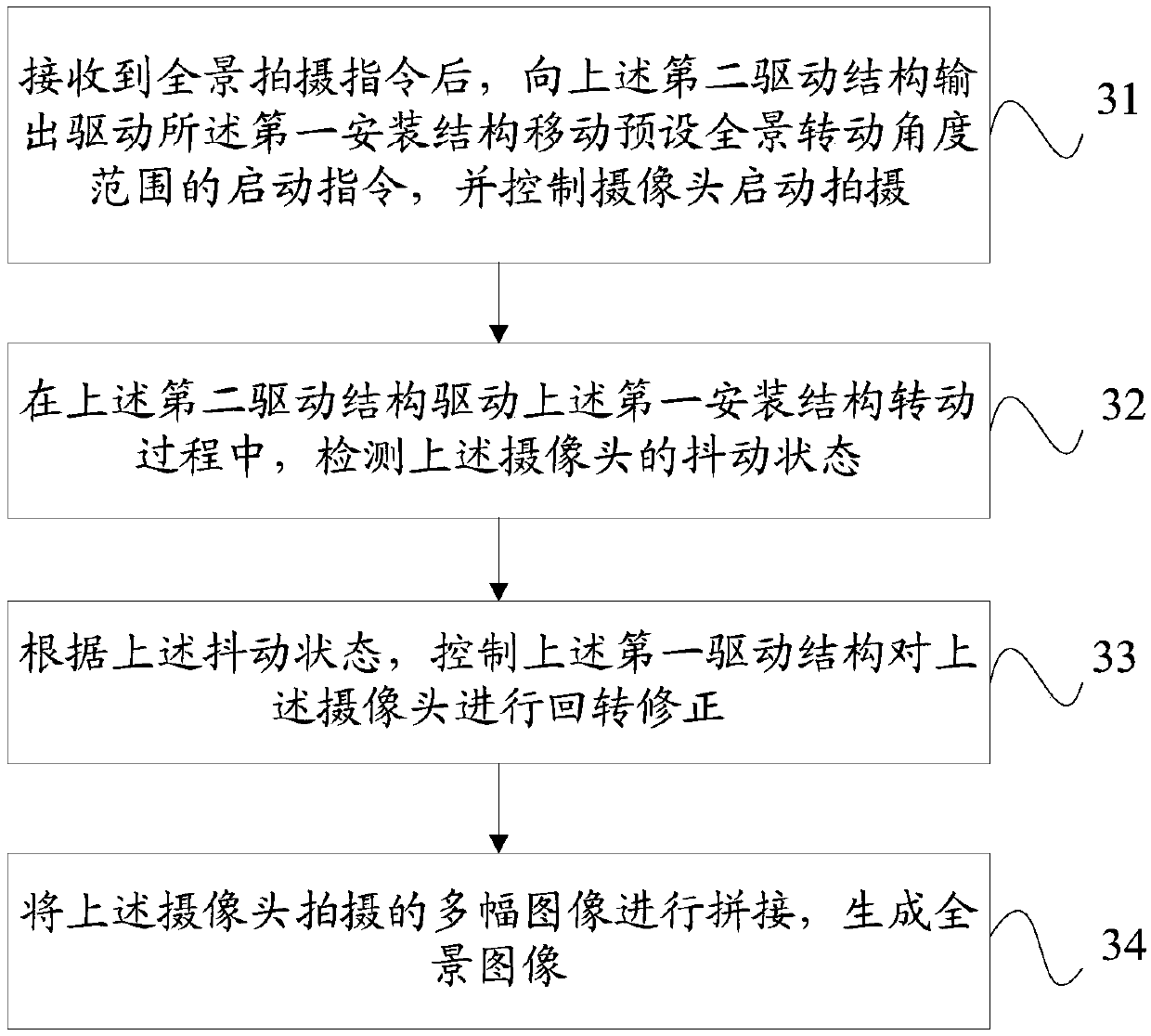
[0045] Embodiments of the present invention also provide a method for panoramic shooting, which is applied to a mobile terminal. The mobile terminal includes the above-mentioned camera control device. The mobile terminal can be specifically a smart phone, a tablet computer, a personal computer, etc., such as image 3 As shown, the method of panoramic shooting includes:
[0046] Step 31: After receiving the panorama shooting instruction, output a starting command to the second driving structure to drive the first installation structure to move the preset panorama rotation angle range, and control the camera to start shooting.
[0047]Specifically, according to the above-mentioned preset panorama rotation angle range, the first angle required to rotate the above-mentioned first installation structure in the first plane can be determined, and output to the above-mentioned second driving structure to drive the above-mentioned first installation structure in the above-mentioned firs...
no. 3 example
[0058] Such as Figure 4 As shown, the panoramic shooting method of the embodiment of the present invention is applied to a mobile terminal, the mobile terminal includes the above-mentioned camera control device, and the mobile terminal can be specifically a smart phone, a tablet computer, a personal computer, etc., and the panoramic shooting method includes:
[0059] Step 41: When it is detected that the shooting mode of the mobile terminal is a panoramic shooting mode, display an area selection interface.
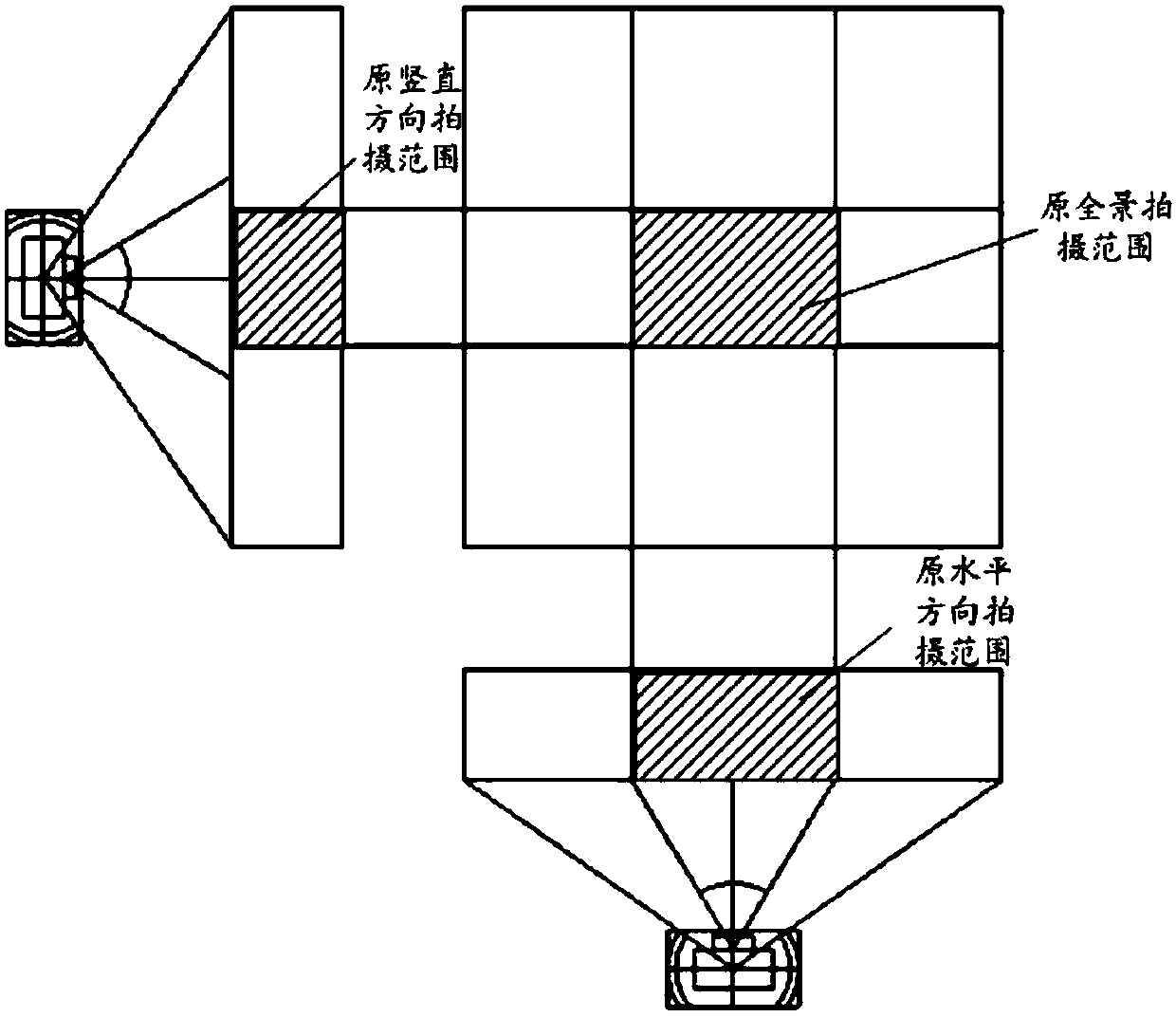
[0060] Such as Figure 5 As shown, there are multiple small rectangles in the lower right corner of the area selection interface, and the largest rectangle formed by the multiple small rectangles is the largest panoramic area that the camera can capture.
[0061] Step 42: Obtain the size of the panorama shooting area selected by the user on the area selection interface.
[0062] In this step, the size of the panoramic shooting area selected by the user may be determined...
PUM
 Abstract
Description
Claims
Application Information
 - R&D
- Intellectual Property
- Life Sciences
- Materials
- Tech Scout
- Unparalleled Data Quality
- Higher Quality Content
- 60% Fewer Hallucinations
Browse by: Latest US Patents, China's latest patents, Technical Efficacy Thesaurus, Application Domain, Technology Topic, Popular Technical Reports.
© 2025 PatSnap. All rights reserved.Legal|Privacy policy|Modern Slavery Act Transparency Statement|Sitemap|About US| Contact US: help@patsnap.com


