Liquid cooling server cluster and data center liquid cooling system

A server cluster, server technology, applied in cooling/ventilation/heating retrofit, electrical equipment enclosure/cabinet/drawer, climate sustainability, etc., can solve problems such as poor cooling performance

Pending Publication Date: 2022-05-27
TIANJIN UNIV OF COMMERCE
View PDF0 Cites 0 Cited by
  • Summary
  • Abstract
  • Description
  • Claims
  • Application Information

AI Technical Summary

Problems solved by technology

[0005] The purpose of the present invention is to provide a liquid-cooled server cluster to solve the technical problem of poor cooling performance of the liquid-cooled server cluster in the prior art

Method used


Image

  • Liquid cooling server cluster and data center liquid cooling system
  • Liquid cooling server cluster and data center liquid cooling system
  • Liquid cooling server cluster and data center liquid cooling system

Examples


Embodiment 1

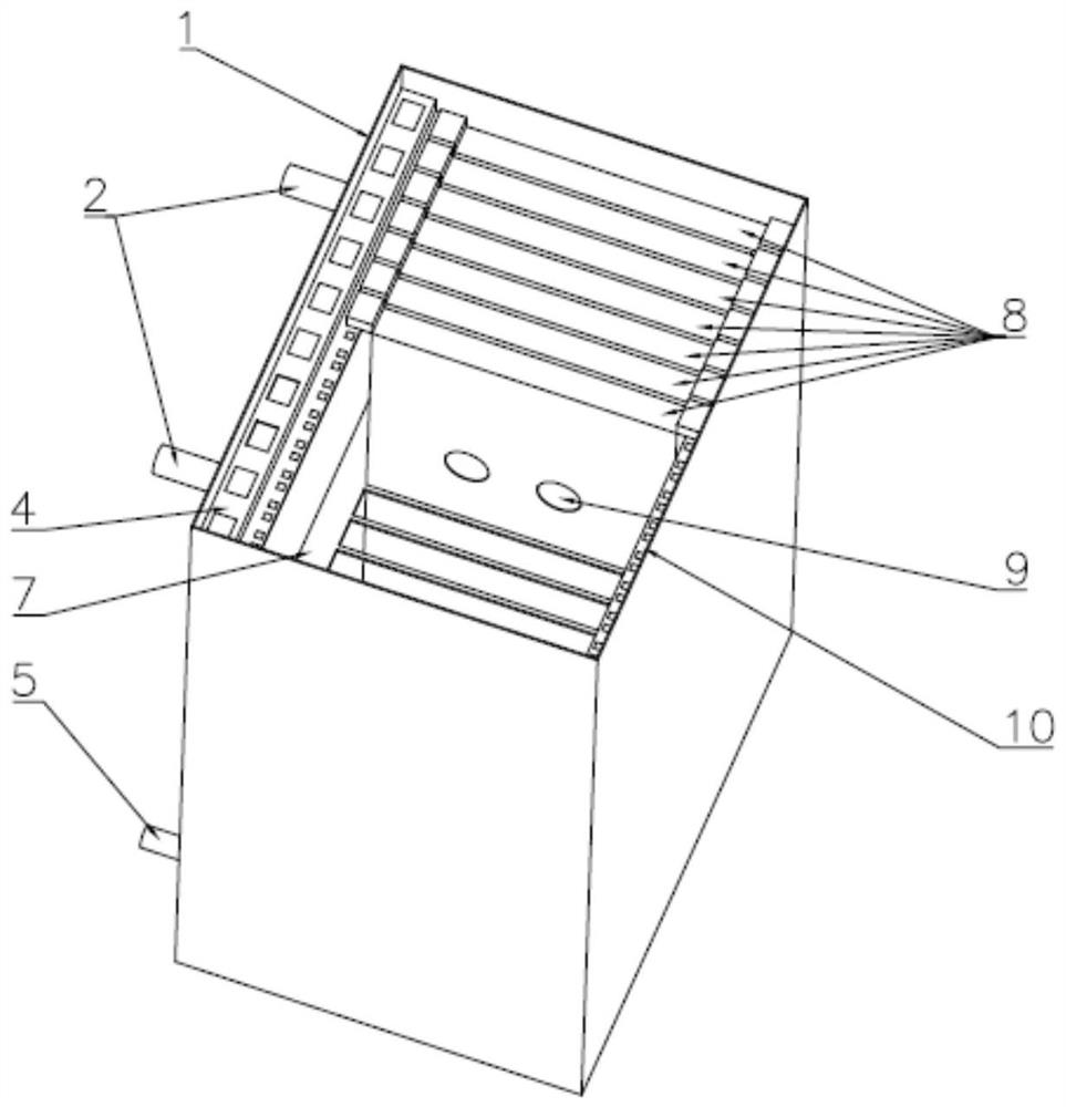
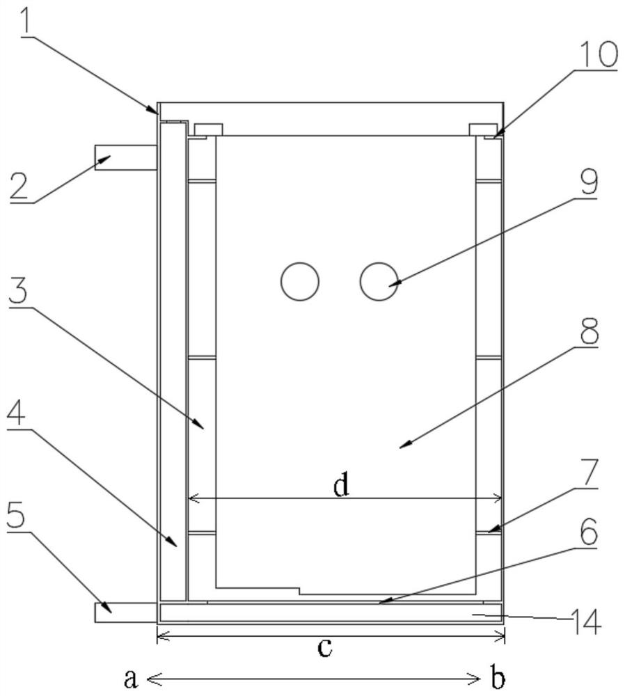
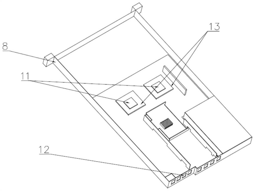
[0036] The liquid cooling server cluster provided in this embodiment, such as Figure 1 to Figure 5 As shown, it includes a cabinet body and a plurality of servers; the cabinet body includes a first cavity, a first plate body 6 is arranged in the first cavity, and a plurality of first through holes are arranged on the first plate body 6; along the vertical direction , the first cavity is divided into mutually independent buffer cavity 14 and immersion cavity 3 by the first plate body 6, and the immersion cavity 3 is located above the buffer cavity 14; a plurality of servers are arranged in the immersion cavity 3; the server includes a casing 8 , the bottom surface of the casing 8 is provided with a second through hole 12, and the bottom surfaces of the plurality of casings 8 are arranged in a one-to-one correspondence with the plurality of first through holes; the immersion chamber 3 is provided with a second plate body 7, and the casing 8 Passing through the second plate body...

Embodiment 2

[0078] The data center liquid cooling system provided in this embodiment includes the liquid cooling server cluster provided in Embodiment 1. Since the buffer cavity 14 and the immersion cavity 3 are independent of each other, after the cooling liquid with a certain flow rate flows into the buffer cavity 14, it can be buffered in the buffer cavity 14, and the buffered cooling liquid flows to the immersion cavity 3 through the first through holes respectively, The distribution of the cooling liquid in the immersion cavity 3 is relatively uniform, and the plurality of first through holes are arranged in a one-to-one correspondence with the bottom surfaces of the plurality of shells 8, so that the second through holes 12 on the bottom surface of each shell 8 can correspond to each other. A first through hole enables multiple servers to obtain the cooling liquid more evenly, so that each server can more fully exchange heat with the cooling liquid, thereby improving the overall cool...


PUM


Abstract

The invention provides a liquid cooling server cluster and a data center liquid cooling system, and relates to the technical field of data center cooling, and the liquid cooling server cluster comprises a cabinet body and a plurality of servers; the cabinet body comprises a first cavity, a first plate body is arranged in the first cavity, and a plurality of first through holes are formed in the first plate body; in the vertical direction, the first cavity is divided into a buffer cavity and an immersion cavity which are independent from each other through a first plate body, and the immersion cavity is located above the buffer cavity; the plurality of servers are arranged in the immersion cavity; the server comprises shells, second through holes are formed in the bottom surfaces of the shells, and the bottom surfaces of the multiple shells correspond to the multiple first through holes one to one; a second plate body is arranged in the immersion cavity, the shell penetrates through the second plate body, and the shell is in sealed connection with the second plate body; and in the vertical direction, the immersion cavities located on the two sides of the second plate body are divided into mutually independent cavities through the second plate body. And each server can exchange heat with the cooling liquid more sufficiently, so that the overall cooling performance of the liquid cooling server cluster is improved.

Description

technical field [0001] The invention relates to the technical field of data center cooling, in particular to a liquid cooling server cluster and a data center liquid cooling system. Background technique [0002] With the rapid development of information technology and the increase of chip integration, the heat flux density of the data center is getting higher and higher, and the traditional air cooling technology can no longer meet the cooling requirements of the data center. Therefore, the cooling technology of data centers has gradually developed into the field of liquid cooling. [0003] In the submerged liquid-cooled server cluster, the server is directly immersed in the insulating cooling liquid, and the higher specific heat of the cooling liquid is used to absorb the heat on the high heat flux components, and then the cooling system cools the cooling liquid to realize the heat transfer. . [0004] In the prior art, a liquid-cooled server cluster includes a cabinet bo...

Claims


Application Information

Patent Timeline
Patent Type & Authority Applications(China)
IPC IPC(8): H05K5/02H05K7/20
CPCH05K7/20218H05K7/20763H05K5/0213Y02D10/00
Inventor 李雪强刘圣春徐智明孙海旺王棋卉
Owner TIANJIN UNIV OF COMMERCE
Why Eureka
Try Eureka