Microchannel heat radiator

A radiator and micro-channel technology, applied in the direction of heat exchanger type, heat exchanger shell, indirect heat exchanger, etc., can solve the problems of insufficient heat exchange of working medium, short residence time of working medium, and low heat exchange efficiency. , to avoid the problem of uneven heat exchange, increase the interaction, and enhance the heat exchange effect.

Inactive Publication Date: 2016-04-27
UNIV OF SHANGHAI FOR SCI & TECH
View PDF8 Cites 9 Cited by
  • Summary
  • Abstract
  • Description
  • Claims
  • Application Information

AI Technical Summary

Problems solved by technology

The design of this heat exchanger has the following disadvantages: 1. This heat exchanger only contains a single-layer microchannel and the channel is linear, and the working fluid stays in the channel for a short time. If it is applied to a vertical working state, due to the action of gravity , its residence time in the tube will be shorter, the working fluid cannot fully exchange heat, and the heat exchange efficiency is not high
2. Each channel is separated from each other, and the fluids in different channels flow through the heat exchanger without any mutual disturbance, the flow form is single, and the heat exchange intensity is limited
[0007] Application number: 201310734806 patent proposes a multi-layer micro-channel condenser. The two ends of the micro-channel tube are respectively equipped with unit headers. Although this heat exchanger adopts the design of multi-layer micro-channels, each channel is Separated by fins, the flow of fluid in different channels is relatively independent, there is no interaction effect, there is less disturbance between fluids, and the heat exchange intensity is not high

Method used


Image

  • Microchannel heat radiator
  • Microchannel heat radiator
  • Microchannel heat radiator

Examples


Embodiment Construction

[0028] The embodiments of the present invention will be described in detail below with reference to the accompanying drawings, but the present invention can be implemented in many different ways defined and covered by the claims.

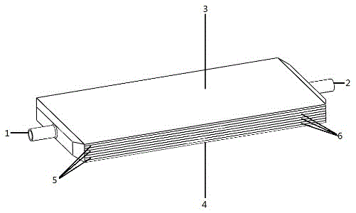
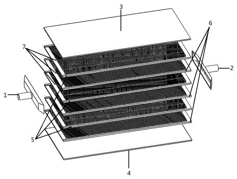
[0029] Depend on figure 1 , figure 2 It can be seen that the radiator in this example consists of a fluid inlet unit 1, a fluid outlet unit 2, an upper cover plate 3, a lower cover plate 4, and rectangular first heat exchange fins 5 and second heat exchange fins 6. composition. A heat dissipation unit is formed by stacking two heat exchange fins in opposite directions. It can be seen from the figure that more than one heat exchange unit is used in this example.

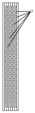
[0030] The fluid inlet and outlet 7 communicate with the fluid inlet unit 1 and the fluid outlet unit 2 respectively, and the fluid can flow from the fluid inlet unit 1 into the radiator, and then flow into the heat exchange fin from the fluid inlet and outlet 7, After heat exchange in ...


PUM


Abstract

The invention relates to the technical field of heat radiation, particularly relates to a microchannel heat radiator and aims at further increasing the efficiency of the existing heat radiating device of an electronic device. The microchannel heat radiator comprises an upper cover plate, a lower cover plate, a fluid feeding unit, a fluid discharging unit and a plurality of heat exchange units, wherein each heat exchange unit is formed by reversely overlapping two heat exchange plates; each heat exchange plate is internally provided with a plurality of partition plates among which runners for allowing fluids to flow are formed; and the adjacent partition plates are intercrossed to form cavities. The partition plates of the adjacent heat exchange plates are crossed to form crossed and interconnected runners, so that the fluids can pass through different heat exchange plates; and due to the adoption of the flowing way, the flow paths of the fluids in the heat radiator are increased, flow routes are optimized, and heat exchange is more sufficient. In addition, due to the adoption of the design, the fluids in different runners can be mutually converged, hedged and dragged, the interaction between every two fluids can be enhanced, and the heat exchange effect can be improved.

Description

technical field [0001] The invention relates to the technical field of heat dissipation, in particular to a microchannel radiator. Background technique [0002] With the rapid development of science and technology, whether it is in electronics or refrigeration equipment, the trend of high integration and high density has become more and more obvious, and the matching heat dissipation requirements are also getting higher and higher. Compared with traditional heat exchangers, microchannel heat exchangers have higher heat transfer efficiency and more economical working fluid consumption, and have gradually been widely researched and applied. [0003] A traditional microchannel radiator consists of a cooling plate with microchannels, a pump for charging and pumping liquid, a cooler, and pipes connecting these devices. The fluid is injected into the microchannel of the heat dissipation cold plate through the pump. The fluid flows in the microchannel to absorb the heat of the hea...

Claims


Application Information

Patent Timeline
Patent Type & Authority Applications(China)
IPC IPC(8): F28D9/00F28F9/22
CPCF28D9/00F28F9/22F28F2009/228
Inventor 崔晓钰朱悦邱子骞
Owner UNIV OF SHANGHAI FOR SCI & TECH
Why Eureka
Try Eureka