Ceramic-matrix high-temperature fused-salt phase-change heat-storage type off-peak electricity utilizing and steam generating device

A technology of steam generating device and ceramic substrate, which is applied in the field of non-oxide ceramic substrate molten salt phase change high-temperature heat storage valley electricity utilization and steam generating device, steam generating device, which can solve the problem that heat transfer oil is not suitable for high temperature conditions, Unstable release process, low heat storage temperature, etc., to achieve good corrosion resistance, reduce heat dissipation loss, and high heat storage density

Active Publication Date: 2016-04-20
SOUTHEAST UNIV
View PDF8 Cites 7 Cited by
  • Summary
  • Abstract
  • Description
  • Claims
  • Application Information

AI Technical Summary

Problems solved by technology

[0004] Purpose of the invention: In order to implement a green and environmentally friendly steam production method, solve the problems of low heat storage temperature, small storage energy, large equipment volume, unstable release process and unsuitable heat transfer oil in the existing phase change heat storage technology (> 400°C), the present invention provides a non-oxide ceramic

Method used


Image

  • Ceramic-matrix high-temperature fused-salt phase-change heat-storage type off-peak electricity utilizing and steam generating device
  • Ceramic-matrix high-temperature fused-salt phase-change heat-storage type off-peak electricity utilizing and steam generating device
  • Ceramic-matrix high-temperature fused-salt phase-change heat-storage type off-peak electricity utilizing and steam generating device

Examples


Embodiment Construction

[0019] In order to describe the technical principles, technical solutions and advantages of the present invention more clearly in detail, the present invention will be described more comprehensively below in conjunction with the accompanying drawings.

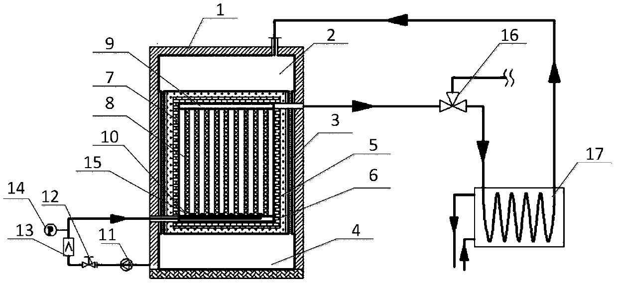
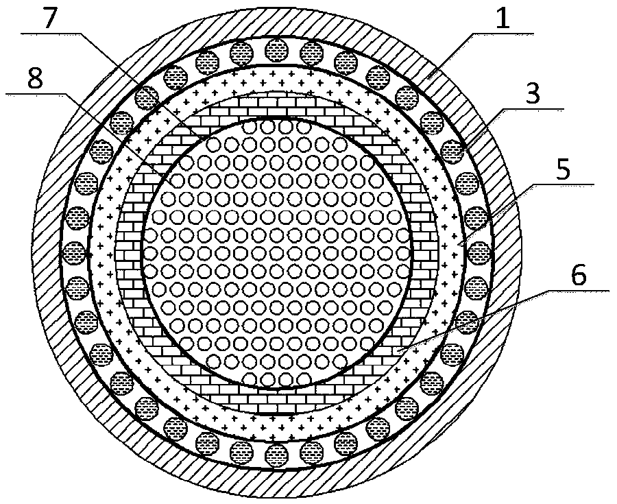
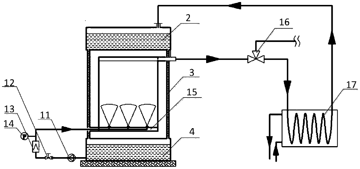
[0020] Such as figure 1 , figure 2 and image 3 As shown in this embodiment, one of the ceramic matrix molten salt phase change high-temperature heat storage type valley electricity utilization steam generating devices disclosed in the embodiment of the invention mainly includes the main body of the heat storage pile, the heat preservation structure of the heat storage pile, the heat transfer medium system and the heat exchanger. heat system. The heat storage reactor is connected to the heat exchange system through steam pipes, and the high-temperature saturated steam in the steam pipes is adjusted through the three-way valve to adjust the flow distribution, which can meet the domestic hot water and steam supply for process ...


PUM


Abstract

The invention discloses a ceramic-matrix high-temperature fused-salt phase-change heat-storage type off-peak electricity utilizing and steam generating device. The ceramic-matrix high-temperature fused-salt phase-change heat-storage type off-peak electricity utilizing and steam generating device comprises a heat-storage pile, a heat-storage pile heat insulation structure, a heat transfer medium system and a heat exchange system. The heat-storage pile comprises a shell and a plurality of heat-storage units, fused salt is packaged inside the heat-storage units, and electric heating devices are arranged on the outer surfaces of the heat-storage units. The heat-storage pile heat insulation structure is arranged on the outer surface of the heat-storage pile and comprises heat conducting bricks, a phase-change heat insulation layer and a water-cooled wall from inside to outside, and the water-cooled wall comprises an upper water tank, a lower water tank and connection water pipes. A water pump of the heat transfer medium system is connected with the lower water tank through a pipeline, and atomizing spray heads are arranged at the bottom of the heat-storage pile and used for spraying atomized soft water into the heat-storage pile. A heat exchanger of the heat exchange system is connected with the heat-storage pile through a steam pipeline and is connected with the upper water tank through a water pipeline, and a three-way valve is arranged on the steam pipeline. The ceramic-matrix high-temperature fused-salt phase-change heat-storage type off-peak electricity utilizing and steam generating device has the advantages that electric energy can be converted into heat energy to be stored during off-peak electricity at night, and heat is obtained after the soft water is atomized during on-peak electricity in the daytime, so that hot water and steam are provided for users.

Description

technical field [0001] The invention relates to a steam generating device, in particular to a non-oxide ceramic matrix molten salt phase change high-temperature heat storage type valley electricity utilization and steam generation device, which belongs to the technical field of valley energy utilization and steam preparation. Background technique [0002] With the rapid development of the economy and the improvement of people's living standards, the society's demand for energy has also increased significantly. However, while the power consumption during the daytime peak period increases sharply, the nighttime valley power is wasted seriously, resulting in a more and more obvious peak-valley difference in power consumption. Generally, power generation, power supply, and power consumption are completed at the same time, so it is difficult to store power. If the generated power is not effectively utilized, it will be lost in the form of grid heating, resulting in a large amount...

Claims


Application Information

Patent Timeline
IPC IPC(8): F22B1/06
CPCF22B1/06
Inventor 陆勇张勉照段文军鹿浩伟
Owner SOUTHEAST UNIV
Why Eureka
Try Eureka