Exhaust channel with aftertreatment system

A technology of exhaust post-treatment and exhaust temperature, which is applied to the electronic control of exhaust treatment devices, exhaust devices, exhaust treatment, etc., can solve the problem of not exceeding the maximum temperature, and achieve the effect of ensuring rapid response behavior

Active Publication Date: 2019-12-27
FORD GLOBAL TECH LLC
View PDF5 Cites 0 Cited by
  • Summary
  • Abstract
  • Description
  • Claims
  • Application Information

AI Technical Summary

Problems solved by technology

The higher the temperature of the LNT, the more efficient the desulfurization treatment, but it cannot exceed the maximum allowable temperature

Method used


Image

  • Exhaust channel with aftertreatment system
  • Exhaust channel with aftertreatment system
  • Exhaust channel with aftertreatment system

Examples


Embodiment Construction

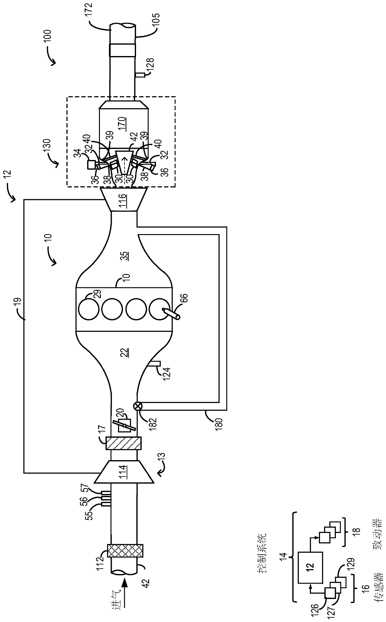
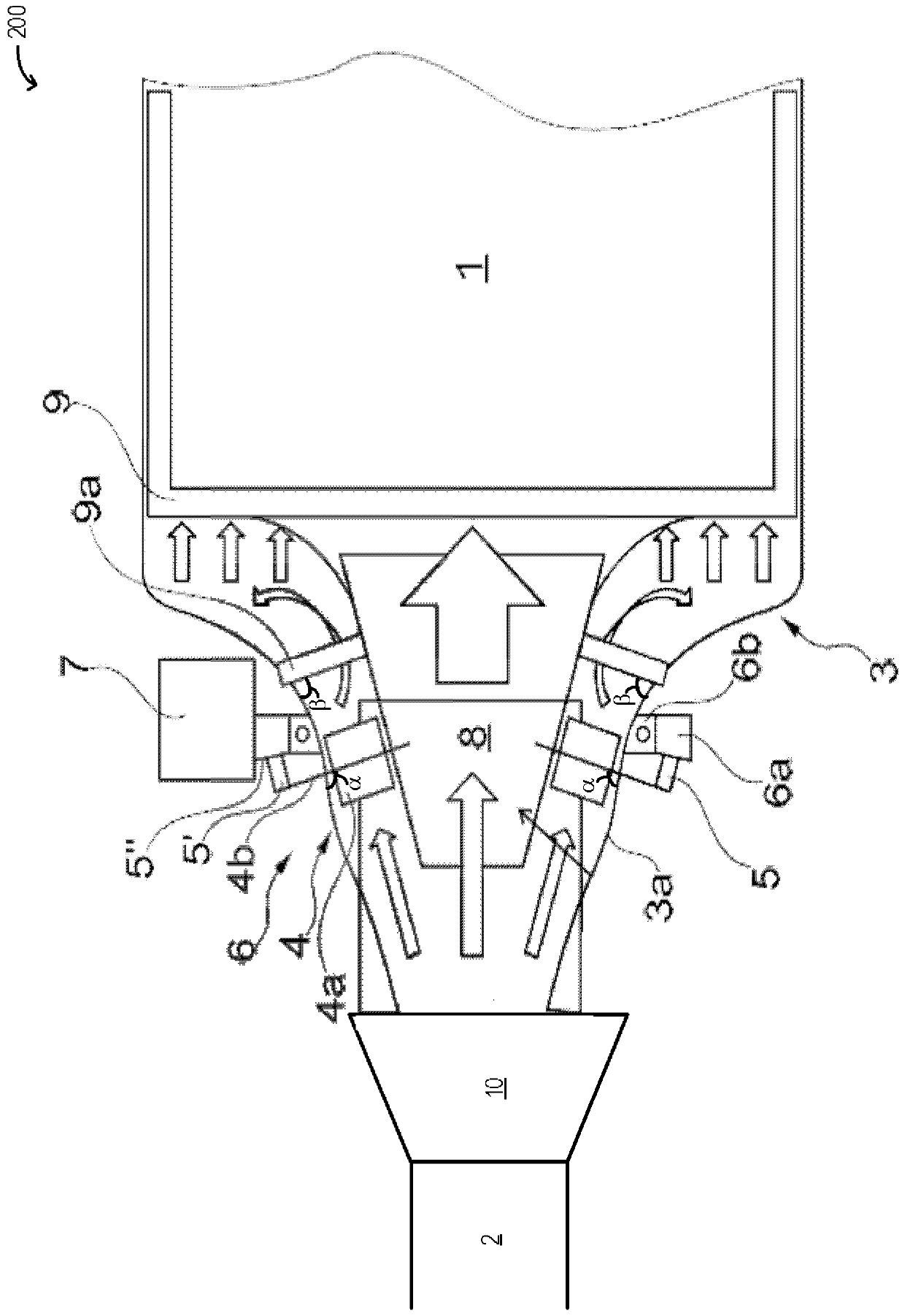
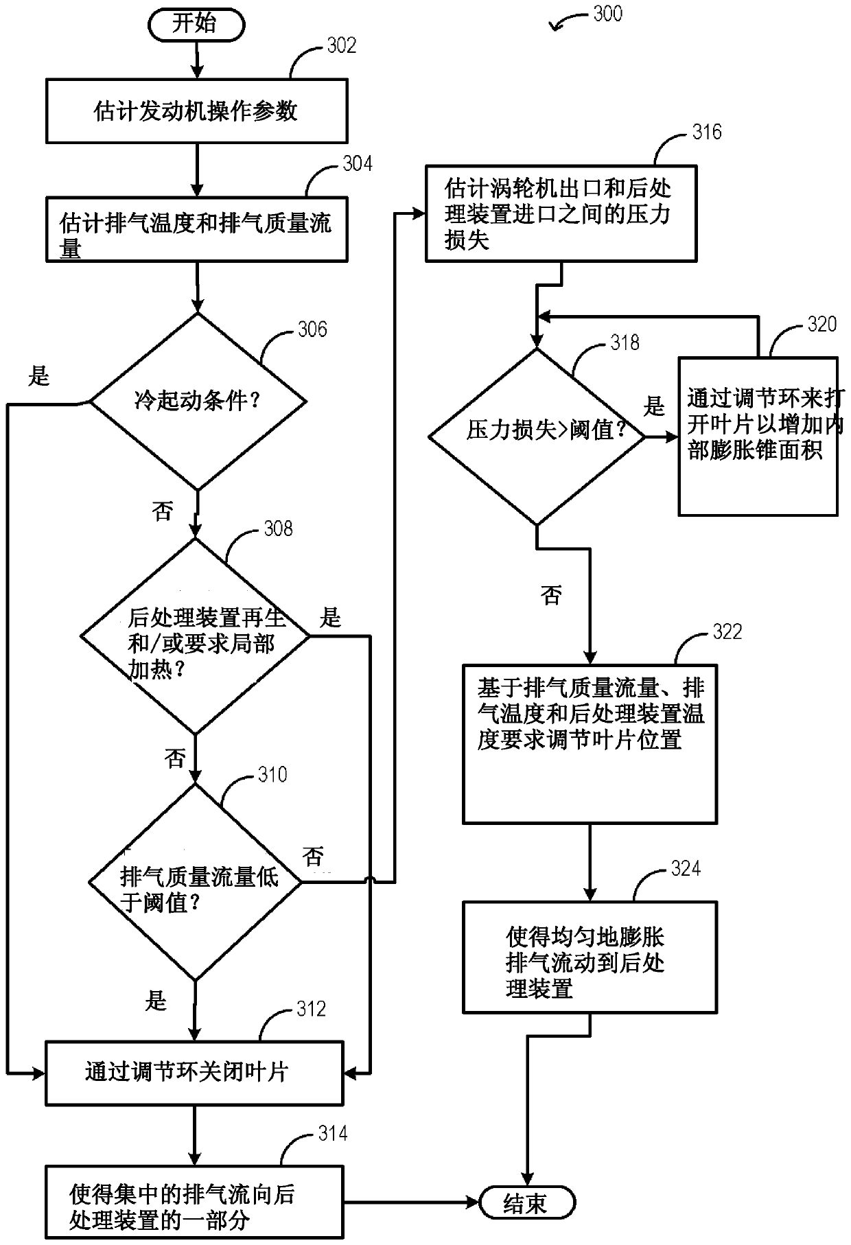
[0055] The following description relates to systems and methods for improving exhaust flow from an outlet of an exhaust turbine via a turbine exit cone to an exhaust aftertreatment device. like figure 2 A longitudinal section of an exemplary engine system including a turbine exit cone with adjustable convoluted blades is shown. The engine controller can be configured to execute control programs such as image 3 The exemplary routine in , adjusts the position (orientation) of the swirling vanes to optimize exhaust flow to the aftertreatment device based on changes in engine operating conditions.

[0056] figure 1 Aspects of an example engine system 100 including engine 10 are schematically shown. In the depicted embodiment, the engine 10 is a booster engine connected to a turbocharger 13 including a compressor 114 driven by a turbine 116 . Specifically, fresh air is drawn into engine 10 along intake passage 42 via air filter 112 and flows to compressor 114 . The compresso...


PUM


Abstract

Methods and systems are provided for regulating exhaust flow from an exhaust turbine outlet downstream to an exhaust aftertreatment device inlet via a compact turbine outlet cone with adjustable convoluted vanes. Exhaust flow to the exhaust aftertreatment device is regulated based on a desired exhaust temperature and an exhaust flow rate at the aftertreatment device. During cold start conditions, the swirl vanes can be closed to focus the exhaust flow towards a portion of the aftertreatment device, while the position of the swirl vanes can be adjusted to direct the exhaust gas flow towards the aftertreatment device after the light-off temperature of the aftertreatment device is reached. Turbulence and homogenization are introduced into the exhaust stream of the aftertreatment device.

Description

[0001] Cross References to Related Applications [0002] This application claims priority from German Patent Application No. 102015207573.7 filed on April 24, 2015, the entire contents of which are hereby incorporated by reference. technical field [0003] The present description generally relates to systems and methods for a turbine exit cone with adjustable convoluted vanes that achieve uniform flow distribution of exhaust flow upstream of an exhaust aftertreatment device. Background technique [0004] The present disclosure relates to an internal combustion engine having an intake system for feeding charge air, an exhaust gas discharge system for discharging exhaust gas and at least one combined exhaust aftertreatment system arranged In the exhaust exhaust system and has an intake housing for feeding exhaust gas. [0005] In the context of the present disclosure, the expression "internal combustion engine" includes diesel engines and spark ignition engines as well as hyb...

Claims


Application Information

Patent Timeline
Patent Type & Authority Patents(China)
IPC IPC(8): F01N9/00F01N3/28F02B37/00
CPCF01N3/28F01N9/00F02B37/00F01N2430/04F01N3/0235F02B37/22F01N3/2006F02B37/18Y02T10/12
Inventor J·克默林F·A·萨默候夫A·库斯克H·M·金德尔V·斯米利亚诺夫斯基F·J·布林克曼
Owner FORD GLOBAL TECH LLC
Why Eureka
Try Eureka