Diaphragm valve
A diaphragm valve, diaphragm technology, applied in the direction of diaphragm valve, diaphragm, balance valve, etc., can solve the problems of large friction, difficulty, limit the lateral size of the valve driver, etc., and achieve the effect of small torque
- Summary
- Abstract
- Description
- Claims
- Application Information
AI Technical Summary
Problems solved by technology
Method used
Image
Examples
Embodiment Construction
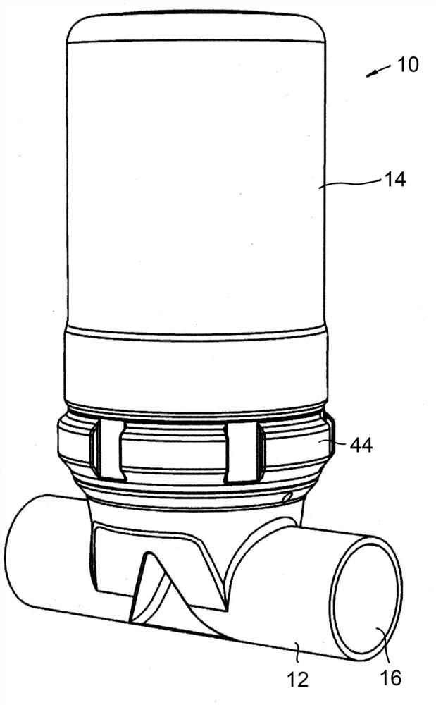
[0037] exist figure 1 A diaphragm valve 10 is shown in , which has a valve body 12 , here in the form of a tube, and a valve drive 14 fastened to the valve body 12 .
[0038] In this embodiment, the valve body is tubular as described and has a flow channel inside it, in which the figure 1 Exit 16 can be seen in . The flow passage can be selectively interrupted or opened in the valve body 12 by the valve driver 14, thereby closing or opening the valve.
[0039] Preferably, this should not be construed as limiting, the valve body 12 may be a one-piece part, deformed or manufactured by casting. Metal or plastic can be used as material.
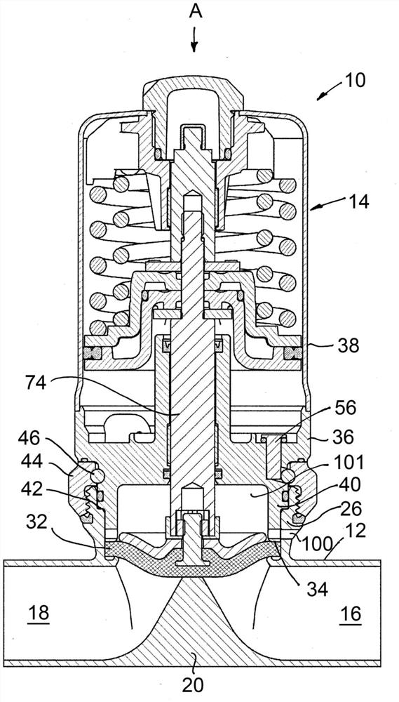
[0040] exist figure 2 In addition to the outlet 16, the inlet 18 of the flow channel can also be seen. A spacer tab 20 extends laterally into the flow channel between the inlet 18 and the outlet 16 and divides the flow channel into two sections. The upper side 22 of the spacer tab (Absperrsteg) 20 (see Image 6 ) outwards to the pipe axis...
PUM
 Abstract
Description
Claims
Application Information
 - R&D
- Intellectual Property
- Life Sciences
- Materials
- Tech Scout
- Unparalleled Data Quality
- Higher Quality Content
- 60% Fewer Hallucinations
Browse by: Latest US Patents, China's latest patents, Technical Efficacy Thesaurus, Application Domain, Technology Topic, Popular Technical Reports.
© 2025 PatSnap. All rights reserved.Legal|Privacy policy|Modern Slavery Act Transparency Statement|Sitemap|About US| Contact US: help@patsnap.com


