Intelligent current transformer polarity tester

A technology of current transformer and tester, applied in the direction of electrical winding testing, instruments, measuring electricity, etc., can solve the problems of unintuitive and clear test phenomenon, small secondary induced current, and more consumption, so as to improve work efficiency and Process quality, high stability and reliability, and the effect of ensuring accuracy

Inactive Publication Date: 2016-11-02
MAINTENANCE BRANCH STATE GRID LIAONING ELECTRIC POWER +1
View PDF5 Cites 4 Cited by
  • Summary
  • Abstract
  • Description
  • Claims
  • Application Information

AI Technical Summary

Problems solved by technology

Due to the large internal resistance of the primary coil, according to Ohm's law I=U / R, the secondary induced current is extremely small, and the pointer of the DC ammeter often swings very little or even without obvious swing, and the test phenomenon is often not intuitive and clear, and even due to relay Due to the technical mistakes of the protection personnel, it is impossible to accurately observe whether the polarity of the CT is correct, and relay protection technicians often spend more time judging the correctness of the polarity of the CT, which makes the work difficult

Method used


Image

  • Intelligent current transformer polarity tester
  • Intelligent current transformer polarity tester

Examples


Embodiment Construction

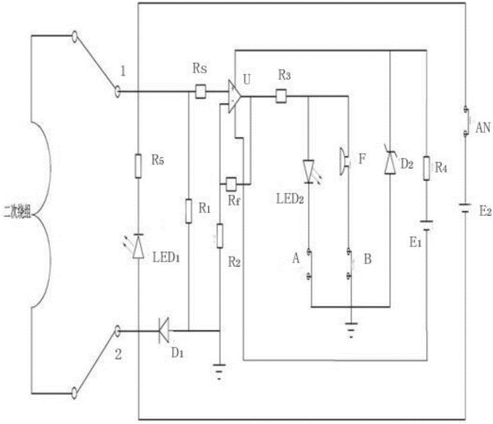
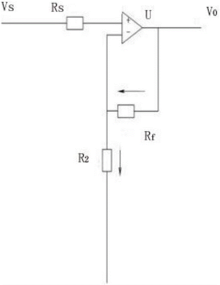
[0015] Such as figure 1 and figure 2 As shown, the intelligent current transformer polarity tester includes positive and negative signal voltage input terminals 1 and 2, and an in-phase proportional amplifier U is connected between the positive and negative signal voltage input terminals 1 and 2 through a current-limiting resistor Rs , the signal voltage is added to the non-inverting input of the same-phase proportional amplifier F through the current-limiting resistor Rs, and a resistor R is connected between the inverting input of the same-phase proportional amplifier U and the system ground 2 , resistor R 2 The negative terminal of the diode D 1 Connected to the negative signal voltage input terminal 2, the resistor R 2 The negative terminal of the diode D 1 The positive terminal is connected to the positive signal voltage input terminal 1 and the resistor R 2 A resistor R is connected between the negative terminals of 1 , the output terminal of the proportional ampl...


PUM


Abstract

The invention provides an intelligent current transformer polarity tester which is easy to operate, stable in operation and visual in test result. A reverse connection prompting circuit is connected between positive and negative signal voltage input ends, and an in-phase proportion amplifier U is connected between the positive and negative signal voltage input ends through a current-limiting resistor Rs and a resistor R2 is connected between the anti-phase input end of the in-phase proportion amplifier U and a system grounding end. The resistor R2 is connected with the negative signal voltage input end through a reverse connection diode D1. A resistor R1 is connected between the positive signal voltage input end and the negative end of the resistor R2. The output end of the in-phase proportion amplifier U is connected with the anti-phase input end of the in-phase proportion amplifier U through a feedback resistor Rf. A resistor R4 and a dry battery E1 are connected in series between the positive and negative power supply ends of the in-phase proportion amplifier U. A self-checking button AN and a dry battery E2 are connected in series between the positive and negative signal power supply input ends. A lighting indication circuit and a sound prompting circuit having a reset function are connected with the output end of the in-phase proportion amplifier U. A voltage stabilizing tube D2 is connected between the positive power supply input end of the in-phase proportion amplifier U and the system grounding end.

Description

technical field [0001] The invention relates to an intelligent current transformer polarity tester, which can effectively test the polarity of the current transformer. Background technique [0002] With the continuous development of science and technology, smart substations emerge as the times require, and electrical devices become more intelligent. The correctness of the CT polarity is directly related to the correctness of the secondary circuit wiring of the measurement, measurement and control, and protection devices. Especially for relay protection and its automatic devices, the correctness of CT polarity is very important. There are two lead-out terminals on the primary and secondary sides of the CT body. The wrong use of the lead-out terminals on either side will cause a 180° change in the secondary current phase, which will cause inaccurate metering circuits, misoperation or refusal of protection devices, resulting in unstable operation of the power grid, and even e...

Claims


Application Information

Patent Timeline
Patent Type & Authority Applications(China)
IPC IPC(8): G01R31/06
CPCG01R31/72
Inventor 王雷李竹勇王振王飞张鹏进石雪明董琪昌姜辉冯振东
Owner MAINTENANCE BRANCH STATE GRID LIAONING ELECTRIC POWER
Why Eureka
Try Eureka