Fingerprint identification display panel and display device

A display panel and fingerprint recognition technology, applied in character and pattern recognition, acquisition/organization of fingerprints/palmprints, optics, etc., can solve problems such as light leakage

Active Publication Date: 2016-11-02
BOE TECH GRP CO LTD
View PDF5 Cites 52 Cited by
  • Summary
  • Abstract
  • Description
  • Claims
  • Application Information

AI Technical Summary

Problems solved by technology

[0004] In view of this, the embodiment of the present invention provides a fingerprint identification display panel and a display device to solve t

Method used


Image

  • Fingerprint identification display panel and display device
  • Fingerprint identification display panel and display device
  • Fingerprint identification display panel and display device

Examples


Embodiment Construction

[0029] The specific implementation manners of the fingerprint identification display panel and the display device provided by the embodiments of the present invention will be described in detail below with reference to the accompanying drawings.

[0030] The shapes and sizes of the components in the drawings do not reflect the true proportions of the fingerprint identification display panel, but are only intended to schematically illustrate the contents of the present invention.

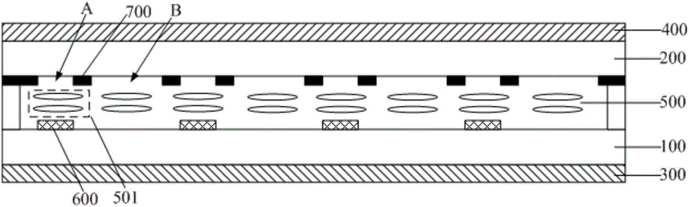
[0031] A fingerprint identification display panel provided by an embodiment of the present invention, such as figure 2 As shown, it includes: the array substrate 100 and the opposite substrate 200 facing each other, the upper polarizer 400 arranged on the side of the opposite substrate 200 away from the array substrate 100, and the liquid crystal layer between the array substrate 100 and the opposite substrate 200 500, a plurality of photosensitive units 600 arranged in an array arranged on the side...


PUM


Abstract

The invention discloses a fingerprint identification display panel and a display device. In a liquid crystal layer arranged at a position corresponding to a first open area, positioned at a place corresponding to a photosensitive induction unit, in a light shielding layer, an initial direction of long axes of liquid crystal molecules is set in such a way that the initial direction and a direction of a light transmission axis of an upper polaroid form an included angle of 45 degrees, and the liquid crystal layer arranged at the position corresponding to the first open area is controlled to form an equivalent quarter wave plate. Linearly polarized light which comes in via the upper polaroid is enabled to be synthesized into circularly polarized light after going through the equivalent quarter wave plate; a rotation state of the circularly polarized light is changed after being reflected via a reflection film layer positioned below the photosensitive induction unit, linearly polarized light which is formed when the circularly polarized light again runs through the equivalent quarter wave plate is perpendicular to the direction of the light transmission axis of the upper polaroid, and therefore the linearly polarized light cannot be emitted out from the upper polaroid and anti-light leakage effects are realized.

Description

technical field [0001] The invention relates to the field of display technology, in particular to a fingerprint identification display panel and a display device. Background technique [0002] With the rapid development of display technology, display panels with a fingerprint recognition function have gradually spread in people's lives. At present, fingerprint recognition display panels generally adopt capacitive structure to realize the function of fingerprint recognition. For example, in-cell fingerprint recognition display The fingerprint identification component is likely to generate parasitic capacitance with the components inside the display panel, so that the fingerprint identification detection signal and the display signal interfere with each other, thereby affecting the quality of fingerprint identification. [0003] Therefore, in order to avoid the above problems, it is possible to utilize the photosensitive characteristics such as the PIN junction, and use photo...

Claims


Application Information

Patent Timeline
IPC IPC(8): G06K9/00
CPCG06V40/1318G02F1/13318G02F1/13338G02F1/133388G06F18/00G02F1/133512G02F1/133528G02F1/1343
Inventor 李昌峰王海生刘英明许睿王鹏鹏卢鹏程
Owner BOE TECH GRP CO LTD
Why Eureka
Try Eureka