
Electrical component

A technology of electrical components and components, applied in the direction of electrical components, circuits, electrical switches, etc., can solve the problems of complex forming mold structure, cutting off and applying of formed products, etc., and achieve the effect of simplifying the mold structure and preventing bad situations.

Active Publication Date: 2016-11-02
ALPS ALPINE CO LTD
View PDF5 Cites 2 Cited by
  • Summary
  • Abstract
  • Description
  • Claims
  • Application Information

AI Technical Summary

Problems solved by technology

[0008] Usually, however, the waterproof cover 904 is manufactured by molding an elastic synthetic rubber material, but when there is an undercut shape portion such as the concave portion 904r of the waterproof cover 904, not only the configuration of the forming die becomes complicated, but also When taking out the molded product, there is a technical problem that a part of the molded product may be chipped off due to the load applied to the undercut shape.

Method used


Image

  • Electrical component
  • Electrical component
  • Electrical component

Examples


no. 1 approach

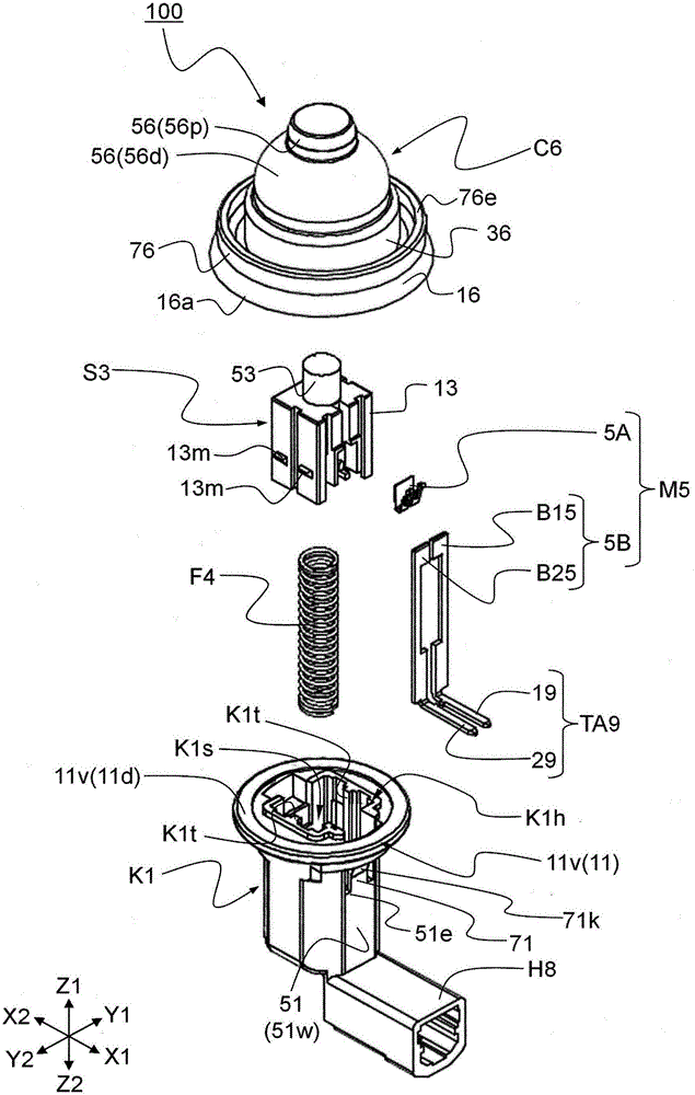
[0108] In the first embodiment of the present invention, the electrical component 100 of the present invention will be described using the drawings. It should be noted that, in the first embodiment of the present invention, the electrical component 100 is a switchgear, but the present invention is not limited thereto.

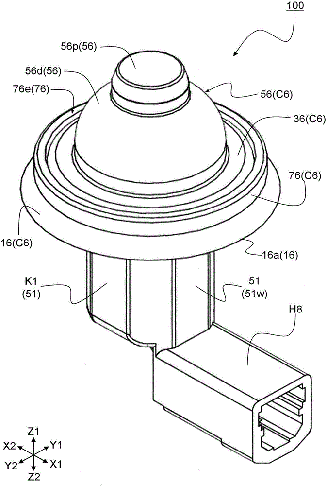
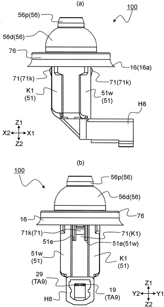
[0109] figure 1 It is an exploded perspective view for explaining the electric component 100 which concerns on 1st Embodiment of this invention. figure 2 is a perspective view of the electrical component 100 . image 3 It is a figure for explaining the electric component 100 of 1st Embodiment of this invention, image 3 (a) is viewed from the Y2 side figure 2 when the main view, image 3 (b) is viewed from X1 side figure 2 time side view. Figure 4 It is a figure for explaining the electric component 100 of 1st Embodiment of this invention, Figure 4 (a) is a perspective view of the mounted portion 500 to which the electrical component 100 is mounted...

no. 2 approach

[0179] Also in the second embodiment of the present invention, the electrical component 200 of the present invention as a switchgear will be described using the drawings.

[0180] Figure 15 It is a perspective view for demonstrating the electrical component 200 which concerns on 2nd Embodiment of this invention. Figure 16 It is a figure for demonstrating the electrical component 200 which concerns on the 2nd Embodiment of this invention, Figure 16 (a) is viewed from the Y2 side Figure 15 when the main view, Figure 16 (b) is viewed from X1 side Figure 15 time side view. Figure 17 It is an exploded perspective view of the electrical component 200 . Figure 18 is along with Figure 6 A longitudinal cross-sectional view of the electrical component 200 cut with the same hatching. Figure 19 is along with Figure 7 A longitudinal cross-sectional view of the electrical component 200 cut with the same hatching. In addition, the electrical component 200 of the second em...

Deformed example 1

[0254] In the above-mentioned first embodiment, a preferred structure is adopted to easily fix the electrical component 100 to the mounted portion 500 using the engaging member 71, but the present invention is not limited thereto, and may be configured such that it is pressed from above the cover member C6, for example. The flange portion 11v of the housing K1 is thus provided with a mounting mechanism restrained from the outside.


PUM


Abstract

The present invention provides an electrical component having a simple structure and a waterproof structure. The electric component (100) is characterized by including a housing (K1) formed with an opening (K1h), an operable member (S3) which is operative, a detecting mechanism (M5) for detecting operation of the operating member and cover member (C6) formed of materials having water resistance and elasticity. The electrical component is mounted on a mounted portion (500) having a mounting hole allowing a housing to be inserted. The housing has a flange portion (11v) formed by projecting outwardly from an outer edge of the housing. The cover member having a base portion (16) formed in a plate shape, a cylindrical portion (36) extending from an inner edge of the base portion and being elastically deformable and a cover portion (56) for closing the cylindrical portion. The outer shape of the cylindrical portion is smaller than the outer shape of the flange portion in a state before the cover member is attached to the housing, and the cylindrical portion is fitted along the outer shape of the flange portion when the cover member is fitted to the housing.

Description

technical field [0001] The present invention relates to electrical components, and more particularly to electrical components suitable for use or placed outside the premises. Background technique [0002] In recent years, electronic devices are increasingly being used or installed outdoors, and the electronic devices are required to have environmental resistance, especially water resistance to water. For example, water resistance against water is required for electrical components that are partially exposed outside the vehicle (outdoors), such as electrical components that detect opening and closing of doors and trunks of automobiles. In view of such circumstances, electrical components having a waterproof structure are becoming more and more important. [0003] As a conventional example of such an electrical component having a waterproof structure, Patent Document 1 proposes a vehicle waterproof key switch 900 mounted on a vehicle body of a door portion and a trunk lid por...

Claims


Application Information

Patent Timeline
Patent Type & Authority Applications(China)
IPC IPC(8): H01H13/06
CPCH01H13/06
Inventor 二宫伸之
Owner ALPS ALPINE CO LTD
Learn More