
A planar structure gain compensation type saw device and its preparation method

A gain compensation, planar structure technology, applied in electrical components, impedance networks, etc., can solve the problems of consistency, poor repeatability, large insertion loss, and difficult debugging, achieving good reliability and repeatability, and small size. Effect

Active Publication Date: 2020-11-10
GUIZHOU MINZU UNIV
View PDF5 Cites 0 Cited by
  • Summary
  • Abstract
  • Description
  • Claims
  • Application Information

AI Technical Summary

Problems solved by technology

[0005] The technical problem to be solved by the present invention: provide a planar structure gain compensation type SAW device and its preparation method to solve the large insertion loss of the surface acoustic wave filter or surface acoustic wave resonator or surface acoustic wave delay line in the prior art In order to solve the problems of consistency, repeatability, poor reliability and difficult debugging caused by the traditional use of external circuit compensation

Method used


Image

  • A planar structure gain compensation type saw device and its preparation method
  • A planar structure gain compensation type saw device and its preparation method
  • A planar structure gain compensation type saw device and its preparation method

Examples


preparation example Construction

[0030] A preparation method of a planar structure gain compensation type SAW device, comprising:

[0031] Step 1. Use IC technology to make LNA on a silicon base or purchase LNA bare chips that meet the compensation requirements;

[0032] Step 2, making a piezoelectric film on the surface of another silicon base;

[0033] Step 3, prepare a layer of metal aluminum film or copper film on the surface of the silicon-based piezoelectric film in step 2 by evaporation or sputtering;

[0034] Step 4, etching the mask pattern of the IDT on the surface of the metal aluminum film or copper film by photolithography;

[0035] Step 5, encapsulation, the LNA in step 1 and the IDT in step 4 are integrated on the same substrate, and packaged.

Embodiment 1

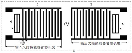
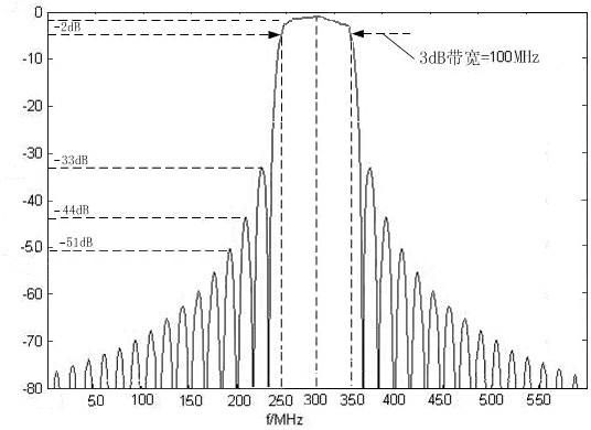
[0037] Taking the rectangular IDT structure as an example, the rectangular IDT structure is as follows figure 2 As shown in the figure, the mark 2 in the figure represents the input interdigital transducer; the mark 3 in the figure represents the output interdigital transducer; the mark 4 in the figure represents the reflection grating; the mark 5 in the figure represents the structure diagram in the dotted frame For the die of the surface acoustic wave filter made to etch the rectangular IDT structure on the surface of the piezoelectric film, the width of the interdigitated electrodes is a, and the electrode interval is b. The amplitude-frequency characteristics of the SAW filter or SAW resonator designed when a=b=7.5 microns and the interdigital logarithm N=30 are as follows: image 3 shown. The substrate material is an AlN piezoelectric film with a C-axis preferential orientation (100). The prepared samples were tested and the results are shown in Table 1.

[0038] Tabl...


PUM


Abstract

The invention discloses a planar structure gain compensation type SAW device and a manufacturing method therefor. The planar structure gain compensation type SAW device comprises an input interdigital energy transducer and an output interdigital energy transducer, both of the input interdigital energy transducer and the output interdigital energy transducer are attached to a surface of piezoelectric material and are coupled to each other via surface acoustic waves, and the output interdigital energy transducer is connected to a matching compensation amplification circuit via a conductor or the input interdigital energy transducer is connected with the matching compensation amplification circuit via the conductor; a defect of large insertion loss of a surface acoustic wave filter or a surface acoustic wave resonator or a surface acoustic wave delay line of the prior art can be overcome; problems of poor consistency, repeatability and reliability and difficult debugging that are caused by traditional use of external circuit compensation of a device can be solved.

Description

technical field [0001] The invention belongs to the technical field of surface acoustic wave devices, and in particular relates to a plane structure gain compensation type SAW device and a preparation method. Background technique [0002] The basic structure of a Surface Acoustic Wave (SAW) device is to make two acoustic-electric and electro-acoustic transducers on the polished surface of a piezoelectric film or a substrate material with piezoelectric properties. In the planar process, a metal film of a certain thickness is evaporated on the surface of the piezoelectric film or the piezoelectric substrate, and the mask patterns of the two designed Inter Digital Transducers (IDT) are etched by photolithography. On the substrate surface, they are used as input transducers and output transducers, respectively. The basic working principle is: the input transducer uses the inverse piezoelectric effect of the crystal to convert the electrical signal into a surface acoustic wave),...

Claims


Application Information

Patent Timeline
Patent Type & Authority Patents(China)
IPC IPC(8): H03H3/02H03H9/02H03H9/10
CPCH03H3/02H03H9/02661H03H9/02818H03H9/1064H03H2003/026
Inventor 王代强童红杨吟野任达森吴燕邓开乐文理为姚祖铭易利亚
Owner GUIZHOU MINZU UNIV
Learn More