Spherical stirring device

A stirring device, a ball-type technology, applied in the directions of transportation and packaging, dissolving, mixer, etc., can solve the problems of inconvenient operation and complex structure, and achieve the effect of simple and convenient operation, simple operation and improved effect.

Inactive Publication Date: 2016-11-09
SOUTH CHINA UNIV OF TECH
View PDF5 Cites 5 Cited by
  • Summary
  • Abstract
  • Description
  • Claims
  • Application Information

AI Technical Summary

Problems solved by technology

However, the current stirring device has a com

Method used


Image

  • Spherical stirring device
  • Spherical stirring device
  • Spherical stirring device

Examples


Embodiment Construction

[0028] For the convenience of those skilled in the art to understand, the present invention will be further described in detail below in conjunction with the accompanying drawings and embodiments.

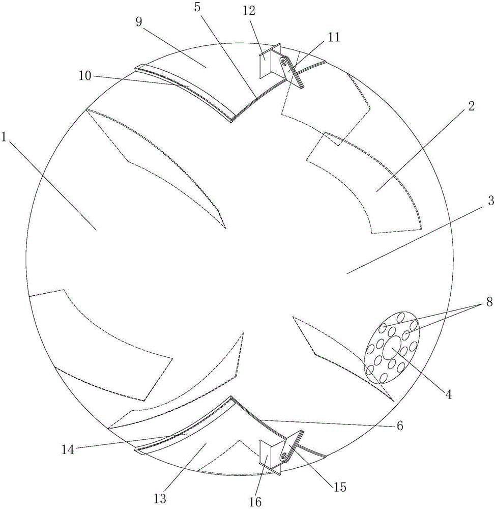
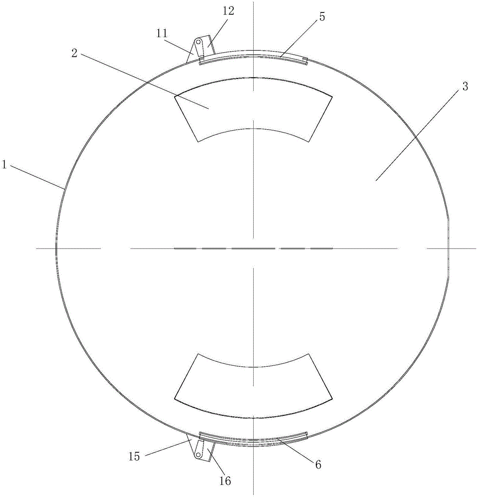
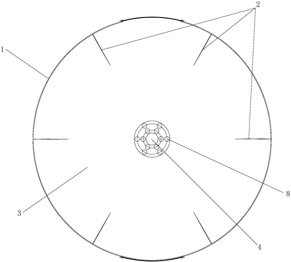
[0029] like Figure 1 to Figure 7 As shown, the spherical stirring device includes a spherical tank body 1 and a plurality of stirring plates 2, the spherical tank body 1 is provided with a stirring chamber 3, and the plurality of stirring plates 2 are evenly installed in the stirring chamber 3 The two ends of described spherical tank body 1 are provided with the rotating shaft hole 4 that is passed by the rotating shaft, between the rotating shaft hole 4 at both ends is provided with inlet and outlet 5 and drain port 6; There are a plurality of ventilation holes 7, and a plurality of spray holes 8 are arranged on the circumference of the other rotating shaft hole 4. Specifically, the stirring chamber 3 matches the shape of the spherical tank body 1 , that is, it is also spherical...


PUM


Abstract

The invention discloses a spherical stirring device. The spherical stirring device comprises a spherical tank and a plurality of stirring plates, wherein a stirring cavity is formed in the spherical tank, the stirring plates are evenly installed in the stirring cavity, rotary shaft holes allowing a rotary shaft to pass through are formed in the two ends of the spherical tank, a material access port and a water drainage port are formed between the rotary shafts holes in the two ends, a plurality of ventilation holes are formed in the periphery of one rotary shaft hole, and a plurality of mist spray holes are formed in the periphery of the other rotary shaft hole. The spherical stirring device is simple in structure, convenient to operate and good in stirring effect.

Description

technical field [0001] The invention relates to a stirring device technology, in particular to a ball stirring device. Background technique [0002] With the rapid development of modern industry, mixing equipment plays an increasingly important role in industrial production. Stirring equipment has a wide range of applications in industrial production, especially in the chemical industry. Many chemical productions use more or less stirring operations. Various chemical changes in the chemical process are based on the premise of sufficient mixing of the reacting substances. For physical changes such as heating, cooling, liquid extraction and gas absorption, stirring operations are often used to obtain good results. The function of general stirring equipment is as follows: to mix the materials uniformly; to disperse the gas well in the liquid phase; to suspend solid particles (such as catalysts) uniformly in the liquid phase; to suspend the immiscible another liquid phase unifo...

Claims


Application Information

Patent Timeline
IPC IPC(8): B01F13/02B01F9/06B01F9/00B01F33/40B01F29/63
CPCB01F29/4011B01F29/63B01F33/402B01F33/4094B01F33/409
Inventor 方利国郑浩然方建炜蔡振培蔡少霞郑灿彬李思敏韦科宇
Owner SOUTH CHINA UNIV OF TECH
Why Eureka
Try Eureka