Lifting and separating device

A separation device and separation chamber technology, applied in the direction of solid separation, used abrasive processing device, transportation and packaging, etc., can solve the problems of unfavorable equipment maintenance and repair, unfavorable attachment cleaning, etc.

Pending Publication Date: 2022-03-22
WUXI FODOO PRECISION IND
View PDF0 Cites 0 Cited by
  • Summary
  • Abstract
  • Description
  • Claims
  • Application Information

AI Technical Summary

Problems solved by technology

[0004] Separation directly at a high position is not conducive to the cleaning of attachments, and is also not conducive to the maintenance and repair of equipment

Method used


Image

  • Lifting and separating device
  • Lifting and separating device
  • Lifting and separating device

Examples


Embodiment Construction

[0022] In order to make the above-mentioned purpose, features and advantages of the present application more obvious and understandable, the specific implementation manners of the present application will be described in detail below in conjunction with the accompanying drawings. In the following description, numerous specific details are set forth in order to provide a thorough understanding of the application. However, the present application can be implemented in many other ways different from those described here, and those skilled in the art can make similar improvements without departing from the connotation of the present application, so the present application is not limited by the specific embodiments disclosed below.

[0023] In the description of the present application, it should be understood that the terms "center", "longitudinal", "transverse", "length", "width", "thickness", "upper", "lower", "front", " Back", "Left", "Right", "Vertical", "Horizontal", "Top", "...


PUM


Abstract

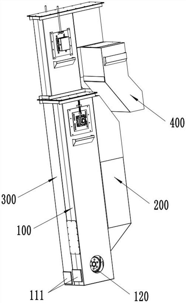
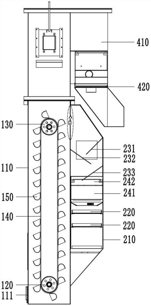
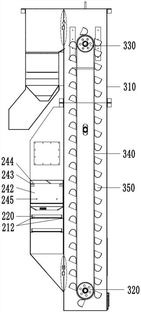
The invention discloses a lifting and separating device which comprises a first-stage lifting mechanism, a first-stage separating mechanism and a second-stage lifting mechanism, the first-stage lifting mechanism can convey mixed materials located at a first station to a second station, the first-stage separating mechanism can receive the mixed materials conveyed by the first-stage lifting mechanism and input the mixed materials into a third station, and the second-stage separating mechanism can receive the mixed materials conveyed by the second-stage lifting mechanism and input the mixed materials into a fourth station. The second-stage lifting mechanism can convey the mixed material at the third station to the fourth station; the first-stage separation mechanism comprises a first-stage separation bin and a first-stage screen, the first-stage separation bin is communicated with the second station and the third station, and when the mixed materials penetrate through the first-stage screen, the materials with large particles can be intercepted. The first-stage separation mechanism is arranged between the high position (the second station) and the low position (the third station), and the mounting position of the first-stage screen can be close to the ground, so that on one hand, the separation condition of mixed materials can be conveniently observed manually, and on the other hand, the first-stage screen can be conveniently cleaned or overhauled by an operator.

Description

technical field [0001] The present application relates to the technical field of material separation, in particular to a lifting separation device. Background technique [0002] Shot blasting machine (also known as sand blasting machine, sandblasting machine) is a casting equipment that uses high-speed projectiles thrown by a shot blasting machine to clean or strengthen the surface of castings. Among them, the projectile is a reusable utensil. However, in the process of the projectile contacting the casting, it will adhere to the attachments on the surface of the casting (such as the scraps scraped off after the casting itself is rubbed, the scraps of the coating on the surface of the casting, or the scraps of the oxide layer on the surface of the casting, etc.). The deposits affect the shot blasting work, and it is necessary to separate the used projectiles to remove the attachments in the projectiles. [0003] Conventional shot blasting machine separation devices are usu...

Claims


Application Information

Patent Timeline
Patent Type & Authority Applications(China)
IPC IPC(8): B07B1/28B07B1/46B24C9/00B22D31/00B65G17/12
CPCB07B1/28B07B1/4663B24C9/006B22D31/00B65G17/126B07B2201/04
Inventor 胡大勇孙浩星
Owner WUXI FODOO PRECISION IND
Why Eureka
Try Eureka