Electric power cabinet

A technology of power cabinets and cabinets, which is applied in the field of electric power, can solve problems such as hidden dangers, temperature rise inside equipment cabinets, and safety issues, and achieve the effects of increasing gravitational potential energy, maintaining operating efficiency, and improving service life

Active Publication Date: 2021-06-04
SHANDONG TAILAI ELECTRIC
View PDF9 Cites 0 Cited by
  • Summary
  • Abstract
  • Description
  • Claims
  • Application Information

AI Technical Summary

Problems solved by technology

[0006] Aiming at the deficiencies of the prior art, the present invention provides a power cabinet, which solves the problem that when the power equipment is running, a large amount of current flows through the power equipment through the wires, so that there is a magnetic field inside the equipment cabinet, and the dust in the air is subjected to the magnetic force of the magnetic field. Attraction enters the interior of the cabinet through the heat dissipation holes, and the dust is magnetically adsorbed on the inner wall of the heat dissipation holes, causing the internal temperature of the equipment cabinet to rise, making the operation of the power equipment unstable, and posing safety hazards. At the same time, rainwater can easily enter the cabinet through the heat dissipation holes If it is exposed to the air for a long time, the heat dissipation holes are easily covered by spider webs, which will affect the heat dissipation inside the power cabinet.

Method used


Image

  • Electric power cabinet
  • Electric power cabinet
  • Electric power cabinet

Examples


Embodiment 1

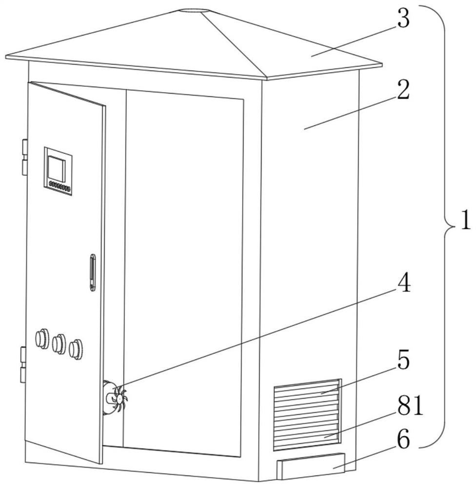
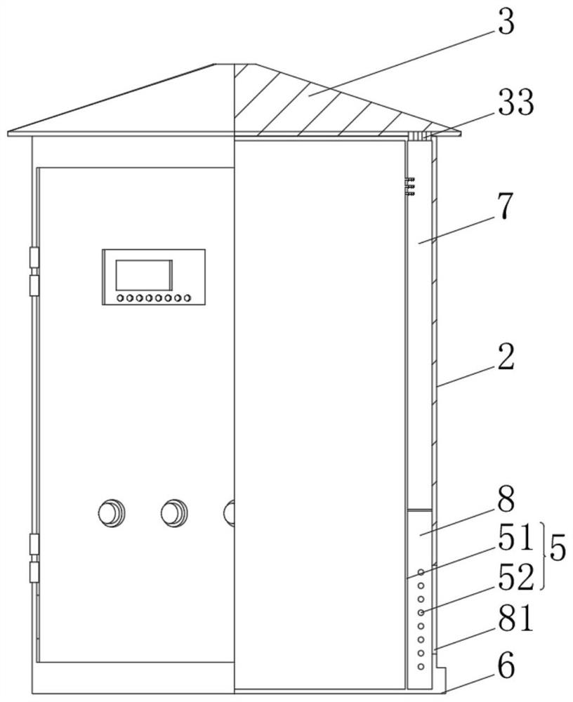
[0039] see Figure 1-3 , the present invention provides a technical solution: a power cabinet, including a power cabinet body 1 composed of a cabinet body 2, a water collection box 3, an exhaust fan 4, an anti-miscellaneous mechanism 5 and a sewage tank 6, the top of the cabinet body 2 and the The bottom of the water receiving box 3 is fixedly connected, the left side of the cabinet body 2 is fixedly connected with the outside of the exhaust fan 4, and the miscellaneous prevention mechanism 5 includes a sealing plate 51, the outside of the sealing plate 51 is fixedly connected with the inside of the cabinet body 2, and the sealing plate The right side of 51 is provided with a blocking mechanism 52, the right side of the sealing plate 51 and the left side of the cabinet body 2 respectively enclose the accumulation water cavity 7 and the flushing water cavity 8, and the right bottom of the flushing water cavity 8 is provided with an air inlet 81 , the water receiving box 3 inclu...

Embodiment 2

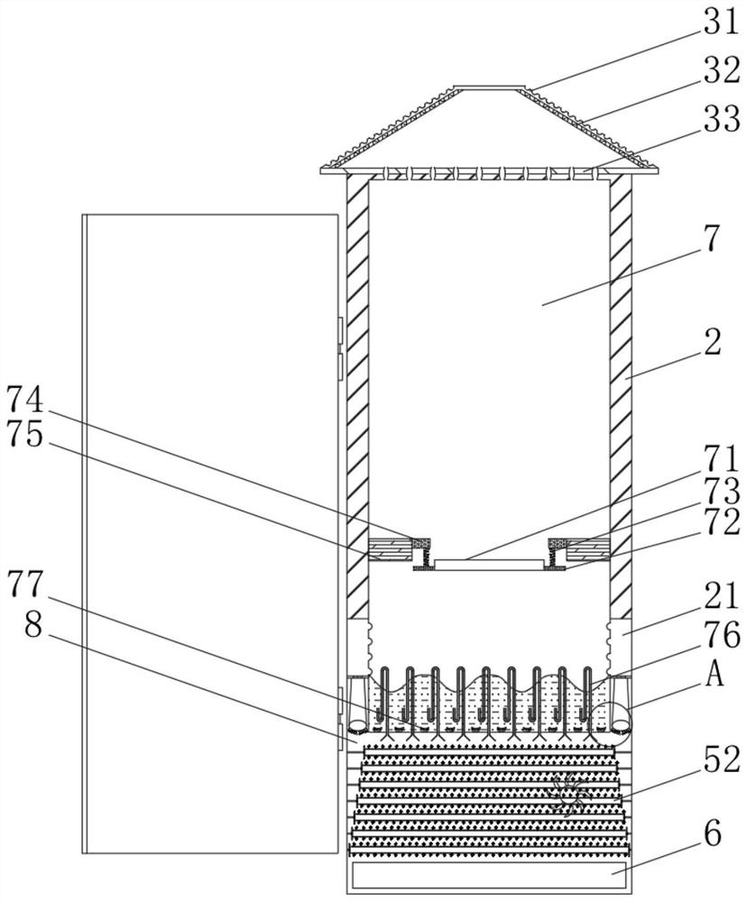
[0045] see Figure 1-4 , on the basis of Embodiment 1, the present invention provides a technical solution: a floating block 77 is provided inside the water storage chamber 7, a water guide mechanism 22 is provided inside the water inlet chamber 21, and the water guide mechanism 22 is connected with the flushing chamber 8 are connected internally.

[0046] The water guiding mechanism 22 includes a drainage tube 221. The top of the drainage tube 221 is fixedly connected to the inner wall of the water inlet chamber 21 through a water guiding plate. 223.

[0047] When in use, the filtered rainwater accumulates water pressure inside the water storage chamber 7 and is released through the water storage plate 71, impacting the bottom of the water storage chamber 7, driving the floating block 77 to float up and down, and the filtered rainwater flows into the drainage through the through hole The tube 221 flows into the water guide bag 222 and flows out of the jet tube 223. The high...

Embodiment 3

[0049] see Figure 1-6 , On the basis of Embodiment 1 and Embodiment 2, the present invention provides a technical solution: the blocking mechanism 52 includes a rotating rod 521, and the outer side of the rotating rod 521 is respectively sleeved with a blade paddle 522 and a vibrating mechanism 9.

[0050] The blade paddle 522 is located outside the vibrating mechanism 9, and the outer end of the rotating rod 521 is rotationally connected with the inside of the flush chamber 8 through a rotating pin.

[0051] The vibrating mechanism 9 includes a vibrating plate 91, an elastic rod 92 is fixedly connected to the outer side of the vibrating plate 91, and a wave ball 93 is fixedly connected to the end of the elastic bar 92 away from the vibrating plate 91, and a vibrating bead 94 is arranged inside the wave ball 93.

[0052] When in use, when the high-pressure water flow impacts the barrier mechanism 52, the blade paddle 522 rotates, drives the vibration mechanism 9 to rotate, dr...


PUM


Abstract

The invention discloses an electric power cabinet which comprises an electric power cabinet body composed of a cabinet body, a water collection box, an exhaust fan, an impurity prevention mechanism and a sewage tank, the top of the cabinet body is fixedly connected with the bottom of the water collection box, the left side of the cabinet body is fixedly connected with the outer side of the exhaust fan, and the impurity prevention mechanism comprises a sealing plate. The invention relates to the technical field of electric power. The electric power cabinet solves the problems that when electric power equipment runs, a large amount of current flows through the electric power equipment through a wire, so that a magnetic field exists in the equipment cabinet, dust in air is attracted by the magnetic force of the magnetic field and enters the cabinet body through the heat dissipation holes, and the dust is attracted to the inner walls of the heat dissipation holes by the magnetic force, so that the internal temperature of the equipment cabinet rises; and the problems of unstable operation of power equipment, potential safety hazards, equipment damage caused by the fact that rainwater easily enters the cabinet body through heat dissipation holes, long-term exposure of the equipment in the air, easy coverage of the heat dissipation holes by spider webs and the like, and further influence on heat dissipation in the power cabinet in the prior art are solved.

Description

technical field [0001] The invention relates to the technical field of electric power, in particular to an electric power cabinet. Background technique [0002] Power distribution cabinets (boxes) are divided into power distribution cabinets (boxes), lighting distribution cabinets (boxes), and metering cabinets (boxes), which are the final equipment of the power distribution system. The power distribution cabinet is a general term for the motor control center. The power distribution cabinet is used in the occasions where the load is relatively scattered and there are few circuits; the motor control center is used in the occasions where the load is concentrated and there are many circuits. They distribute the electric energy of a certain circuit of the upper-level power distribution equipment to the nearest load. This level of equipment shall provide protection, monitoring and control of the load. [0003] According to Chinese patent CN112018644A, the present invention pro...

Claims


Application Information

Patent Timeline
Patent Type & Authority Applications(China)
IPC IPC(8): H02B1/28B08B3/02B08B3/10B08B7/02H02B1/56H02B1/30
CPCH02B1/28B08B3/02B08B3/102B08B7/02H02B1/565H02B1/30
Inventor 不公告发明人
Owner SHANDONG TAILAI ELECTRIC
Why Eureka
Try Eureka