
Cutting machine for fan shell

A technology for cutting machines and casings, applied in metal sawing equipment, sawing machine devices, metal processing equipment, etc., can solve the problems of affecting work efficiency and inability to adjust the angle of the main disk, so as to improve efficiency, improve fixing efficiency, and accurate angle Effect

Inactive Publication Date: 2016-11-09
WUXI ZUNBAO ELECTRIC VEHICLE CO LTD
View PDF0 Cites 0 Cited by
  • Summary
  • Abstract
  • Description
  • Claims
  • Application Information

AI Technical Summary

Problems solved by technology

[0002] At present, the appearance of fans on the market is various, and the size and shape of the shell iron sheets used are also different. Therefore, it is necessary to use a cutting machine for effective cutting to complete the iron sheet cutting of the appearance of the fan. The cutting machine is also called a cutting saw. The relative angle relationship between the cutting blade and the working turntable can be divided into vertical cutting machine and oblique cutting machine. The saw blade of the vertical cutting machine cuts perpendicular to the working turntable, so the angle cannot be adjusted relative to the working main disk. Both iron sheet and mobile cutting machine will affect work efficiency

Method used


Image

  • Cutting machine for fan shell
  • Cutting machine for fan shell
  • Cutting machine for fan shell

Examples


Embodiment Construction

[0014] The following will clearly and completely describe the technical solutions in the embodiments of the present invention with reference to the accompanying drawings in the embodiments of the present invention. Obviously, the described embodiments are only some, not all, embodiments of the present invention. Based on the embodiments of the present invention, all other embodiments obtained by persons of ordinary skill in the art without making creative efforts belong to the protection scope of the present invention.

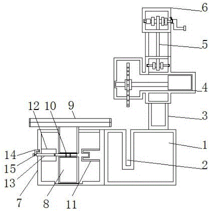
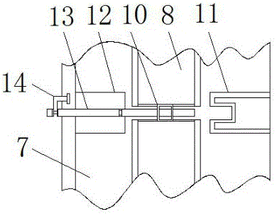
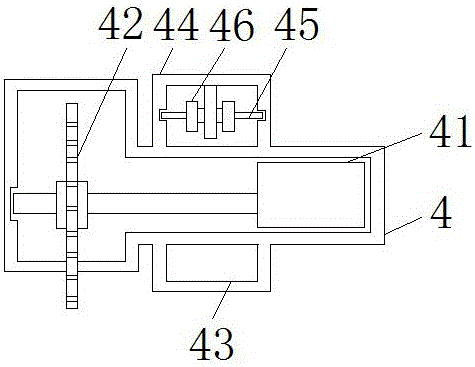
[0015] see Figure 1-4 , the present invention provides a technical solution: a cutting machine for the fan casing, including a cutting table 1, the top of the cutting table 1 is provided with a cutting groove 2, when cutting materials, the cutting piece 42 and the cutting groove 2 form a groove It is more convenient and efficient when cutting. The upper surface of the cutting table 1 is fixedly connected with the bottom end of the fixed frame 3. The fixed fra...


PUM


Abstract

The invention discloses a cutting machine for a fan shell. The cutting machine for the fan shell comprises a cutting table, wherein a cutting groove is formed in the top end of the cutting table; the upper surface of the cutting table is fixedly connected with the bottom end of a fixing rack; a cutting machine body slidably sleeves the fixing rack; a stretching device is fixedly mounted at the top end of the fixing rack; one side of the cutting table is fixedly connected with one side of a material box; the bottom of a cavity of the material box is slidably connected with the bottom end of a movable shaft; and the top end of the movable shaft penetrates through the material box, extends to the outer side of the top end of the material box and is fixedly connected with the bottom of a shaft center of a material table. According to the cutting machine for the fan shell, the movable shaft drives the material table to rotate, and is fixed through a fixed rod, the fixed rod is fixed by a fixing valve, after first cutting is finished, the stretching device which is fixedly mounted on the fixing rack drives the cutting machine body to move upwards, by two fixing devices, the movable shaft fixing efficiency is improved, and therefore, the cutting angle is accurate.

Description

technical field [0001] The invention relates to the technical field of fan processing, in particular to a cutting machine for a fan casing. Background technique [0002] At present, the appearance of fans on the market is various, and the size and shape of the shell iron sheets used are also different. Therefore, it is necessary to use a cutting machine for effective cutting to complete the iron sheet cutting of the appearance of the fan. The cutting machine is also called a cutting saw. The relative angle relationship between the cutting blade and the working turntable can be divided into vertical cutting machine and oblique cutting machine. The saw blade of the vertical cutting machine cuts perpendicular to the working turntable, so the angle cannot be adjusted relative to the working main disk. Both iron sheets and mobile cutters will affect work efficiency. Contents of the invention [0003] The purpose of the present invention is to provide a cutting machine for fan ...

Claims


Application Information

Patent Timeline
Patent Type & Authority Applications(China)
IPC IPC(8): B23D45/02B23D47/02B23D47/04
CPCB23D45/025B23D47/025B23D47/047
Inventor 沈利锋
Owner WUXI ZUNBAO ELECTRIC VEHICLE CO LTD
Learn More