Blade polishing device based on pneumatic control

A technology of pneumatic control and polishing device, applied in grinding automatic control device, grinding/polishing safety device, grinding driving device, etc. High quality of power supply, effect of suppressing frost and icing

Active Publication Date: 2016-11-09
江苏智光创业投资有限公司
View PDF6 Cites 6 Cited by
  • Summary
  • Abstract
  • Description
  • Claims
  • Application Information

AI Technical Summary

Problems solved by technology

Existing blade polishing devices often have problems such as too complex structure, high cost, and high operating cost

Method used


Image

  • Blade polishing device based on pneumatic control
  • Blade polishing device based on pneumatic control
  • Blade polishing device based on pneumatic control

Examples


Embodiment 1

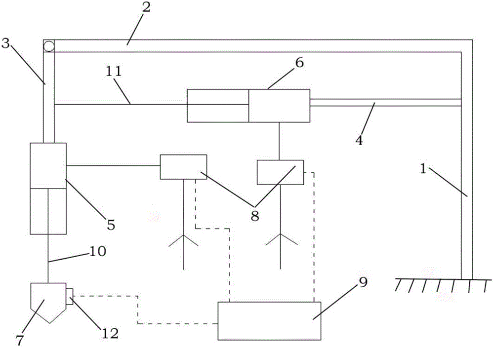
[0025] Such as figure 1 A blade polishing device based on pneumatic control shown includes a fixed beam 1, a beam 2, a first connecting rod 3, a second connecting rod 4, a first cylinder 5, a second cylinder 6, a polishing tool 7, and a control valve 8 and the controller 9; the fixed beam 1 is vertically arranged and fixedly connected with the horizontally arranged crossbeam 2, the crossbeam 2 is hinged with the first connecting rod 3, the first connecting rod 3 is fixedly connected with the first cylinder 5, and the second The connecting rod 6 is fixedly connected with the second cylinder 6 and the fixed beam 1 respectively; the piston of the first cylinder 5 is fixedly connected with the polishing tool 7 through the first transmission rod 10, and the piston of the second cylinder 6 is fixed through the second transmission rod 11 is fixedly connected with the second connecting rod 4; the first cylinder 5 and the second cylinder 6 are both driven by the control valve 8; during...

Embodiment 2

[0033] Such as figure 1A blade polishing device based on pneumatic control shown includes a fixed beam 1, a beam 2, a first connecting rod 3, a second connecting rod 4, a first cylinder 5, a second cylinder 6, a polishing tool 7, and a control valve 8 and the controller 9; the fixed beam 1 is vertically arranged and fixedly connected with the horizontally arranged crossbeam 2, the crossbeam 2 is hinged with the first connecting rod 3, the first connecting rod 3 is fixedly connected with the first cylinder 5, and the second The connecting rod 6 is fixedly connected with the second cylinder 6 and the fixed beam 1 respectively; the piston of the first cylinder 5 is fixedly connected with the polishing tool 7 through the first transmission rod 10, and the piston of the second cylinder 6 is fixed through the second transmission rod 11 is fixedly connected with the second connecting rod 4; the first cylinder 5 and the second cylinder 6 are both driven by the control valve 8; during ...

Embodiment 3

[0041] Such as figure 1A blade polishing device based on pneumatic control shown includes a fixed beam 1, a beam 2, a first connecting rod 3, a second connecting rod 4, a first cylinder 5, a second cylinder 6, a polishing tool 7, and a control valve 8 and the controller 9; the fixed beam 1 is vertically arranged and fixedly connected with the horizontally arranged crossbeam 2, the crossbeam 2 is hinged with the first connecting rod 3, the first connecting rod 3 is fixedly connected with the first cylinder 5, and the second The connecting rod 6 is fixedly connected with the second cylinder 6 and the fixed beam 1 respectively; the piston of the first cylinder 5 is fixedly connected with the polishing tool 7 through the first transmission rod 10, and the piston of the second cylinder 6 is fixed through the second transmission rod 11 is fixedly connected with the second connecting rod 4; the first cylinder 5 and the second cylinder 6 are both driven by the control valve 8; during ...


PUM


Abstract

A blade polishing device based on pneumatic control is characterized by comprising a fixing beam, a cross beam, a first connecting rod, a second connecting rod, a first air cylinder, a second air cylinder, a polishing tool, a control valve and a controller, wherein the fixing beam is arranged vertically and fixedly connected with the horizontally arranged cross beam; the cross beam is hinged to the first connecting rod; the first connecting rod is fixedly connected with the first air cylinder; the second connecting rod is fixedly connected with the second air cylinder and the fixing beam; a piston of the first air cylinder is fixedly connected with the polishing tool through a first transmission rod; a piston of the second air cylinder is fixedly connected with the second connecting rod through a second transmission rod; and the first air cylinder and the second air cylinder are supplied with air and driven by the control valve. During work, the position of the polishing tool is changed by pushing the pistons of the first air cylinder and the second air cylinder, and therefore the contact force between the polishing tool and a blade is changed.

Description

technical field [0001] The invention relates to the field of blade polishing, in particular to a blade polishing device based on pneumatic control. Background technique [0002] Blade polishing is an important process of blade processing. During the processing of blades, due to various reasons, the blade margin may be uneven, and even the margin may be too thick or too thin on a workpiece. This requires Polish the blades. Existing blade polishing devices often have problems such as too complicated structure, too high cost, and high operating cost. Contents of the invention [0003] In view of the above problems, the present invention provides a blade polishing device based on pneumatic control. [0004] The object of the present invention adopts following technical scheme to realize: [0005] A blade polishing device based on pneumatic control is characterized in that it includes a fixed beam, a beam, a first connecting rod, a second connecting rod, a first cylinder, a ...

Claims


Application Information

Patent Timeline
Patent Type & Authority Applications(China)
IPC IPC(8): B24B19/14B24B29/02B24B41/02B24B55/02B24B55/00B24B49/16B24B51/00B24B47/14
CPCB24B19/14B24B29/02B24B41/02B24B47/14B24B49/165B24B51/00B24B55/00B24B55/02
Inventor 不公告发明人
Owner 江苏智光创业投资有限公司
Why Eureka
Try Eureka