Flue forming device and flue forming method using same

A molding device and molding method technology, applied to ceramic molding cores, ceramic molding machines, ceramic molding mandrels, etc., can solve the problems of low mechanized production efficiency, large investment in manpower and material resources, and difficulty in extracting internal molds, and achieve simplified Forming steps, improved production efficiency, simple and convenient operation

Inactive Publication Date: 2016-11-09
合肥超威光电科技有限公司
View PDF7 Cites 5 Cited by
  • Summary
  • Abstract
  • Description
  • Claims
  • Application Information

AI Technical Summary

Problems solved by technology

Most of the existing flue prefabrication molds use the outer mold and the inner mold to form a cavity in the shape of the flue 1, and then inject the slurry into the cavity. Since the inner mold is in contact with the inner wall of the flue 1, the manual operation space is limited to the flue 1. In the inner cavity 2, it is difficult to extract the inner mold
At the same time, when using the existing flue forming device for flue production, the operation of removing the inner mold is complicated, the requirements for equipment are high, the investment in manpower and material resources is large, and the efficiency of mechanized production is not high

Method used


Image

  • Flue forming device and flue forming method using same
  • Flue forming device and flue forming method using same
  • Flue forming device and flue forming method using same

Examples


Embodiment Construction

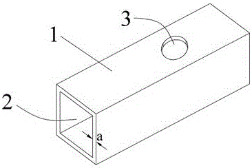
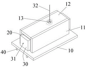
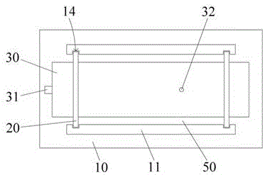
[0036] Such as figure 2 , 3 As shown, the flue forming device includes an outer mold and an inner mold. The outer mold includes a base plate 10, and the base plate 10 is provided with two side plates 11 parallel to each other. The side plates 11 are detachably fixed on the base plate 10, and the side plates 11 Two detachable baffles 20 are provided at both ends. The baffles 20 are hollow frames. The baffles 20 are provided with a cover plate 12 parallel to the bottom plate 10. The cover plate 12 is provided with a grout that penetrates the surface of the plate. Port 13, the dotted line in the grouting port 13 area is the position of the flue hole 3 after the flue is formed, the inner mold is an inflatable cylinder 30, and the cylinder 30 is in the shape of the inner wall of the flue after inflation, the bottom plate 10, the baffle plate 20, The cover plate 12 and the column body 30 together form a flue cavity 50, which is the cavity formed by the flue. By using the column 3...


PUM


Abstract

The invention relates to a flue forming device and a flue forming method using the same, and belongs to the field of building devices. The flue forming device comprises an outer formwork and an inner formwork. The outer formwork comprises a bottom plate; two parallel side plates are arranged on the bottom plate; the side plates are detachably fixed to the bottom plate; two detachable baffles are arranged at the two ends of each side plate; the baffles are hollow frame bodies; cover plates parallel to the bottom plate are arranged on the baffles; and grouting openings penetrating through plate surfaces are formed in the cover plates. The inner formwork is an inflatable column body; after inflation, the column body is in a flue inner wall shape; and the bottom plate, the baffles, the cover plates and the column body together define a flue cavity. The inflatable column body is designed to serve as the inner formwork, and the inner formwork can be taken down from the inner wall of a flue conveniently after forming of the flue. The invention further provides the flue forming method using the flue forming device. The flue forming method comprises the steps of outer formwork splicing, inner formwork inflation, bottom layer slurry injection, fully filling of slurry, and inner formwork and outer formwork dismounting.

Description

technical field [0001] The invention relates to a construction machinery device, in particular to a flue forming device. The invention also relates to two flue forming methods using the flue forming device, belonging to the field of construction devices. Background technique [0002] Houses generally use the flue to remove the smoke generated by the cooking activities in the kitchen or the turbid air in the bathroom. The flue structure is as follows: figure 1 As shown, the flue 1 is surrounded by four sides, and the wall thickness of each side is a. There is a cavity 2 inside the flue 1, and the gas is discharged to the outside of the house through the cavity 2. On the side of the flue 1 A flue hole 3 is provided, and its function is to connect a range hood or an exhaust fan. [0003] Due to the simple structure of the flue, it is generally used in building construction after being prefabricated with molds according to construction requirements. Most of the existing flue p...

Claims


Application Information

Patent Timeline
Patent Type & Authority Applications(China)
IPC IPC(8): B28B7/18B28B7/32B28B1/00B28B1/14
CPCB28B7/18B28B1/00B28B1/14B28B7/0002B28B7/32
Inventor 王祥生
Owner 合肥超威光电科技有限公司
Why Eureka
Try Eureka