Stapler convenient for stapling

A stapler and convenient technology, applied in the direction of bookbinding, can solve the problems of increasing labor intensity of workers, affecting the quality of bookbinding, and high labor intensity of workers, so as to improve the quality and aesthetics of bookbinding, improve the efficiency of installation, and realize bookbinding. automated effects

Active Publication Date: 2016-11-09
HUZHOU JIANING PRINTING
15 Cites 4 Cited by

AI-Extracted Technical Summary

Problems solved by technology

At present, printing factories usually use small staplers for manual binding, which not only has low binding efficiency, but also causes poor aesthetics of finished products after binding due to the different positions of workers each time. The strength is different, it is easy to damage the paper and affect the quality of binding
In addition, for the beauty of the bound matter, a plastic book holder is usually placed on the bound printed matter, which is not only beautiful, but also ensures ...

Abstract

The invention discloses a stapler convenient for stapling. The stapler comprises a base (1), wherein a stapling platform (2) is arranged on the base (1); input rails (3) are arranged at two ends of the stapling platform (2); an output rail (4) is arranged on one side of the stapling platform (2); a stapling device is arranged on the other side of the stapling platform (2), and comprises a bracket (5) with a hydraulically telescoping structure; a sliding rail (6) is arranged at the upper end of the bracket (5); and a group of staple pressing assemblies are arranged on the sliding rail (6). The stapler convenient for stapling has the characteristics of improving the stapling efficiency, improving the stapling quality, reducing the labor intensity of a worker and enhancing the aesthetic property of a stapled object.

Application Domain

Technology Topic

Image

  • Stapler convenient for stapling
  • Stapler convenient for stapling
  • Stapler convenient for stapling

Examples

  • Experimental program(1)

Example Embodiment

[0022] The present invention will be further described below in conjunction with the drawings and embodiments, but it will not serve as a basis for limiting the present invention.
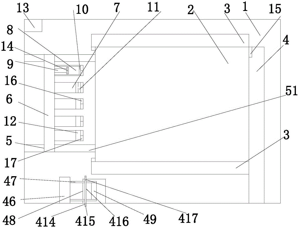
[0023] Examples. A stapler that is convenient for binding, constituted as Figure 1 to Figure 9 As shown, it includes a base 1, a binding platform 2 is provided on the base 1, an input rail 3 is provided at both ends of the binding platform 2, an output rail 4 is provided on one side of the binding platform 2, and a binding device is provided on the other side of the binding platform 2 , The binding device includes a bracket 5 with a hydraulic telescopic structure, the upper end of the bracket 5 is provided with a sliding track 6, a set of nail pressing components are arranged on the sliding track 6, the nail pressing assembly includes a needle storage part 7, and the needle storage part 7 is provided with a needle storage groove 8. There is a hydraulic push rod 9 in the needle storage groove 8, a needle outlet 10 is arranged at the end of the needle storage groove 8, and a pressure needle 11 is arranged above the needle outlet 10, and the pressure needle 11 is connected with a hydraulic cylinder 12, a hydraulic cylinder 12 A controller 13 is connected; the end of the hydraulic push rod 9 is provided with a pressure sensor 14, the pressure sensor 14 is connected to the controller 13, and the controller 13 is connected to the hydraulic push rod 9; the output track 4 is provided with a distance measuring device 15. The distance measuring device 15 is connected to the controller 13; the end of the nail pressing component is provided with an infrared sensor 16, the infrared sensor 16 is connected to the controller 13, and the bracket 5 is connected to the controller 13; Buzzer 17 on the nailing assembly.
[0024] The input rail 3 includes a fixed rail 31 fixed on the base 1, a hydraulic adjusting rod 32 is provided on both sides of the fixed rail 31, a movable rail 33 is provided at the upper end of the hydraulic adjusting rod 32, and the lower surface of the movable rail 33 is on the fixed rail 31 Each surface is provided with a rolling wheel 34, the rolling wheel 34 is connected with a motor, and the motor and the hydraulic adjusting rod 32 are connected with the controller 13; the movable track 33 is provided with a distance detector 35, which is connected with the controller 13; A limit sensor 36 is provided at the end of the fixed rail 31, and the limit sensor 36 is connected to the controller 13.
[0025] The output rail 4 includes a second fixed rail 41 fixed on the base 1, a second hydraulic adjusting rod 42 is provided on both sides of the second fixed rail 41, and a second movable rail 43 is provided at the upper end of the second hydraulic adjusting rod 42, The lower surface of the second movable rail 43 and the upper surface of the second fixed rail 41 are both provided with a second rolling wheel 44, the second rolling wheel 44 is connected with a motor, and the motor and the second hydraulic adjusting rod 42 are connected with the controller 13; A second distance detector 45 is provided on the two movable rails 43, and the second distance detector 45 is connected to the controller 13.
[0026] The side of the binding platform 2 is provided with a T-shaped moving groove 21, a moving bracket 22 is arranged in the moving groove 21, a hydraulic rod 23 is connected to the moving bracket 22, a pressure wheel 24 is connected to the hydraulic rod 23, and a pressure wheel 24 is connected to the hydraulic rod 23. A second infrared sensor 25 is provided. The second infrared sensor 25 and the hydraulic lever 23 are connected to the controller 13; the movable bracket 22 is provided with a movable wheel 26 contacting the movable groove 21, and the movable wheel 26 is connected with a motor. Connected to the controller 13.
[0027] The outlet of the output rail 4 is provided with a plastic book clip installation device. The plastic book clip installation device includes a book clip storage chamber 46. The bottom end of the book clip storage chamber 46 is provided with a moving rail 47. The moving rail 47 is connected with a mounting plate 48. The plate 48 is provided with a fixed groove 49 connected to the moving rail 47, a telescopic groove 410 is provided on one side of the fixed groove 49, a hydraulic telescopic rod 411 is provided in the telescopic groove 410, and a fixed plate 412 is provided at the end of the hydraulic telescopic rod 411; The mounting plate 48 is provided with sliding grooves 413 on both ends, a mounting frame 414 is provided on the sliding groove 413, a second hydraulic rod 415 is provided on the mounting frame 414, and a movable plate 416 is provided on the second hydraulic rod 415; A laser rangefinder 417 is provided on the board 416, and the laser rangefinder 417 is connected to the controller 13.
[0028] The moving rail 47 is provided with a tripod 418 corresponding to the shape of the book holder. An opening 419 is provided at the end of the tripod 418. A hydraulic expansion rod 420 is provided at the opening 419, and the hydraulic expansion rod 420 is connected to the controller 13.
[0029] The base 1 is provided with a horizontal sliding rail 51, and the bracket 5 is located above the horizontal sliding rail 51.
[0030] The horizontal slide rail 51 is provided with a driving wheel connected to the support 2, the driving wheel is connected with a motor, and the motor is connected with the controller 13.
[0031] The moving track 47 is provided with a third motor, and the third motor is connected to the controller.
[0032] The mounting frame 414 is provided with a pulley in contact with the chute, the pulley is connected with a second motor, and the second motor is connected with the controller.
[0033] The working principle of the present invention: arrange the paper to be bound and put it into the fixed track 31 on the input track 3, and detect the distance between the movable track 33 and the paper by the distance detector 35 on the movable track 32, and the controller 13 according to the signal Control the expansion and contraction of the hydraulic adjustment lever 32 to adjust the distance between the movable rail 33 and the paper, and then start the motor to drive the scroll wheel to drive the paper forward. When the paper touches the limit sensor 36, the controller 13 controls the motor to stop moving. Then, the controller 13 drives the hydraulic lever 24 to adjust according to the data of the second infrared sensor 25, and then the controller 13 controls the fourth motor to drive the moving wheel 26 to move, thereby driving the pressing wheel 24 to move, and perform adjustment on the paper on the side that needs to be bound. Squeeze to make the paper adhere more closely to each other and facilitate binding. After the squeezing is finished, the controller makes corresponding commands to the binding device according to the corresponding commands input by the user and then according to the signals of the distance measuring device 15 and the infrared sensor 16. The bracket 5 adjusts the height according to the commands of the controller 13, and presses the nails. The component adjusts the corresponding position on the transverse slide rail 51 according to the command, and then the hydraulic cylinder 12 outputs the corresponding pressure to press the needle, and finally the binding is completed. Start the output track 4, before the output track 4 drives the bound paper to be output, the controller 13 first controls the tripod 418 on the moving track 47 to move, the tripod 418 moves the book holder into the fixed slot 49, and then the controller 13 The hydraulic expansion rod 420 is controlled to expand to open the book clip opening, and then the fixed plate 412 and the movable plate 416 are extended into the book clip opening, and the controller 13 controls the second hydraulic rod 415 to contract, thereby keeping the book clip opening open. Then start the output track 4 to drive the paper output, and the binding position on the paper enters the book holder. When the paper reaches the end of the book holder, the laser rangefinder 417 transmits the signal to the controller 13, and the controller 13 controls the pulley and the hydraulic telescopic rod 411 moves so that the movable plate 416 and the fixed plate 412 leave the book holder, completing the installation of the book holder.

PUM

no PUM

Description & Claims & Application Information

We can also present the details of the Description, Claims and Application information to help users get a comprehensive understanding of the technical details of the patent, such as background art, summary of invention, brief description of drawings, description of embodiments, and other original content. On the other hand, users can also determine the specific scope of protection of the technology through the list of claims; as well as understand the changes in the life cycle of the technology with the presentation of the patent timeline. Login to view more.

Similar technology patents

Guide buckle and terminal sheath with same

ActiveCN102856728AImprove binding efficiencyCoupling device detailsEngineering
Owner:BYD CO LTD

Port binding method and system for multi-port USB equipment

PendingCN112650702AImprove binding efficiencySimple processElectric digital data processingEngineeringUSB
Owner:BEIJING HUADA ZHIBAO ELECTRONICS SYST +1

Information processing method, device and equipment and readable storage medium

ActiveCN112584350AImprove binding efficiencyReduce error rateParticular environment based servicesVehicle infrastructure communicationIntelligent transportIn vehicle
Owner:APOLLO INTELLIGENT CONNECTIVITY (BEIJING) TECH CO LTD

High-weather-resistance automotive paint

InactiveCN109627902AImprove weather resistanceImprove binding efficiencyAnti-corrosive paintsEpoxy resin coatingsChemical activityWeather resistance
Owner:安徽超哥精密科技有限公司

Classification and recommendation of technical efficacy words

  • Improve binding efficiency

Method and system for binding Internet of Things service machine card

PendingCN110446200AThe binding process is simpleImprove binding efficiencyNetwork data managementInternet of ThingsMSISDN
Owner:WATCHDATA SYST +1

Automatic rebar binding machine

PendingCN107587721AHigh degree of automationImprove binding efficiencyBuilding material handlingRebarAutomation
Owner:福建谊和天宸科技有限公司

Conversion layer large-span section steel concrete beam and construction method thereof

ActiveCN110700490AImprove binding efficiencyEasy to operateGirdersJoistsRebarLap joint
Owner:武汉市盘龙明达建筑有限公司
Why Eureka
Try Eureka