Rainwater remover for automobile windshield

A windshield and clearer technology, applied in the automotive field, can solve the problems of troublesome replacement and maintenance, long wiper length, wiper scraping, etc., and achieves the effects of reduced maintenance and replacement costs, longer service life, and convenient disassembly and assembly.

Inactive Publication Date: 2016-11-09
嘉兴智慧园区营运管理有限公司
View PDF5 Cites 6 Cited by
  • Summary
  • Abstract
  • Description
  • Claims
  • Application Information

AI Technical Summary

Problems solved by technology

Due to the large size of the wiper, the wiper after using it for a long time will easily generate a noise on the glass surface. When the wiper swings back and forth, there will be an interval, that is, the time when the wiper swings past and the time when it swings back. A gap period is formed between this. Therefore, during this period of time, the rainwater hits the car window and cannot be wiped off by the wiper. Therefore, during this interval, the driver's vision through the glass is blurred.
[0003] Although the wiper is divided into slow, medium, fast, and three gears, no matter how fast the fast gear is, it cannot eliminate the intermediate interval. Moreover, the length of the wiper is long, and the speed is too fast, which will easily lead to a greatly shortened life of the wiper. loud rubbing sound
[0004] In addition, the existing wiper can only be fixed on the car window, and can only be used in one place. It cannot be disassembled and cannot be used in other places. It is troublesome to replace and maintain.

Method used


Image

  • Rainwater remover for automobile windshield
  • Rainwater remover for automobile windshield
  • Rainwater remover for automobile windshield

Examples


Embodiment 1

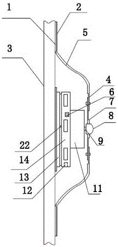
[0035] figure 1 It is a schematic diagram of the overall assembly structure of the first embodiment, figure 1 Among them, a fixing device, a power drive device and a cleaning device are included. The fixing device is used to fit the windshield 3 of the car. Since the windshield 3 has a relatively smooth surface, the fixing device selects a sealing suction cup 13, and the sealing suction cup 13 has an adsorption chamber 19 inside, and when in contact with the windshield 3, the adsorption is mainly completed through the adsorption chamber 19;

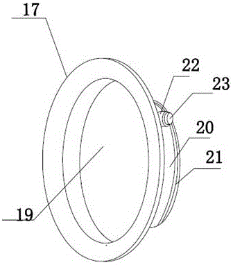
[0036] Such as figure 2 As shown, since the sealing suction cup 13 is made of silica gel material, the texture is relatively soft, so in order to effectively fix the power drive device installed on one side, a protective casing 20 is specially arranged on the back of the sealing suction cup, and the protective casing 20 is hard. quality metal material, the inside of the sealed suction cup 13 is embedded in the protective shell 20;

[...

Embodiment 2

[0059] Such as Image 6 as shown, Image 6 It is the second deformation method of the fixing device. In order to ensure the fixing force between the whole device and the windshield surface, more than one suction cavity 18 is specially set on the edge part of the sealing suction cup, and the suction cavity 18 adopts an inner concave structure;

[0060] In order to be able to absorb, in this embodiment, the thickness of the edge part can be increased. After the concave suction cavity contacts the glass surface, it can absorb the glass surface, and the suction cavity is preferably around the edge part. set so that the edge portion can have a uniform fixing capacity in all directions;

[0061] The function and structure of these suction cavities are the same as those of ordinary small suction cups, and it is not easy to make the suction cavities too large, otherwise it will affect the sealing performance of the sealing suction cup;

[0062] Figure 7 as shown, Figure 7 It is...

Embodiment 3

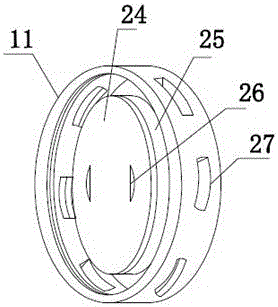
[0066] Figure 8 It is a schematic structural diagram of a sealed suction cup according to Embodiment 3 of the present invention;

[0067] Figure 8 Among them, the sealing suction cup is another deformation structure, the main purpose is to set up an independent auxiliary suction structure, and set more than one lug 33 around the outside of the edge part, and the suction cavity 32 is set on the lug 33 , the purpose of which is to reduce the influence of the suction cavity 32 on the adsorption of the sealing suction cup, so that it can have an independent auxiliary fixing structure;

[0068] The contact area between the entire sealing suction cup and the windshield surface is also greatly increased, so its adsorption capacity will also be greatly increased, such as Figure 8 As shown, this structure makes the installation more uniform, and its sealing effect is better than that in the first embodiment and the second embodiment.

[0069] In embodiment 3, other structures are...


PUM


Abstract

The invention discloses a rainwater remover for an automobile windshield. The rainwater remover for the automobile windshield comprises a detachable remover body which is installed on the automobile windshield or on glass on the two sides. The remover body comprises a fixing device, a power driving device and a removing device. The fixing device comprises a sealing suction cup. An adsorption cavity is formed in the sealing suction cup. The interior of the sealing suction cup is embedded in a protective shell. The sealing suction cup is provided with a protruding edge part. An air hole is formed in the position, right facing a vacuum cavity, outside the sealing suction cup. A sealing plug is arranged in the air hole for sealing the air hole. The air hole is used for being connected with an external vacuumizing device and used for pumping out air in the adsorption cavity. External threads are arranged and assembled on the outer side of the protective shell. By installing the rainwater remover on any glass surface of an automobile window, rainwater on the glass surface can be removed rapidly so that a driver can drive an automobile without obstacles, the problem of interruption appearing when a windscreen wiper swings is solved, and the rainwater remover can be dismounted and mounted in use.

Description

technical field [0001] The invention relates to the field of automobiles, in particular to an automobile windshield rainwater remover. Background technique [0002] In the prior art, automobiles are equipped with wipers. When the wipers are working, they swing the wipers back and forth along a pivot point. Two wipers are generally used to scrape the rainwater on the windshield back and forth. Due to the large size of the wiper, the wiper after using it for a long time will easily generate a noise on the glass surface. When the wiper swings back and forth, there will be an interval, that is, the time when the wiper swings past and the time when it swings back. A gap period is formed between this. Therefore, during this period of time, when rainwater hits the car window, it cannot be scraped off by the wiper. Therefore, during this interval, the driver's vision through the glass is blurred. [0003] Although the wiper is divided into slow, medium, fast, and three gears, no ma...

Claims


Application Information

Patent Timeline
Patent Type & Authority Applications(China)
IPC IPC(8): B60S1/04
CPCB60S1/04
Inventor 严润达吴燕婷
Owner 嘉兴智慧园区营运管理有限公司
Why Eureka
Try Eureka