Chain bucket reclaiming equipment and corresponding ship unloader

A chain bucket and equipment technology, applied in the field of reclaiming equipment, can solve the problems of ineffective unloading, structural damage, low utilization rate of the wharf, etc., and achieve the effect of improving the efficiency of unloading, controlling dust overflow, and high utilization rate of wharf

Active Publication Date: 2018-03-13
SHANGHAI MARITIME UNIVERSITY
View PDF7 Cites 0 Cited by
  • Summary
  • Abstract
  • Description
  • Claims
  • Application Information

AI Technical Summary

Problems solved by technology

For large bulk carriers, due to the large turning radius of unloading in this way, adjacent cabin operations cannot be realized, and the utilization rate of the terminal is low.
The chain tensioning method of the L-type chain bucket ship unloader is to realize the chain tensioning through the oil cylinder, but because the oil cylinder tensioning device is located in the cabin, dust can easily enter the hydraulic pipeline, causing hydraulic system failure. Practice has proved that hydraulic tensioning The failure rate of the method is high, which seriously affects the unloading efficiency of the terminal
[0008] The chain bucket lifting method of the existing L-shaped chain bucket ship unloader is to realize the amplitude improvement of the L-shaped material taking head through the oil cylinder, and realize the overall lifting of the entire front arm and the L-shaped material taking head through the luffing oil cylinder, but Due to the lagging response of the oil cylinder action, the L-shaped chain bucket reclaimer and the front outrigger can be regarded as rigid structures. Once encountering the jacking force caused by the surge, they cannot be effectively unloaded, thus causing damage to the structure.
Unable to adapt to unloading operations in seaports

Method used


Image

  • Chain bucket reclaiming equipment and corresponding ship unloader
  • Chain bucket reclaiming equipment and corresponding ship unloader
  • Chain bucket reclaiming equipment and corresponding ship unloader

Examples


Embodiment Construction

[0032] Hereinafter, in conjunction with the accompanying drawings, a preferred embodiment is described in detail to further illustrate the present invention.

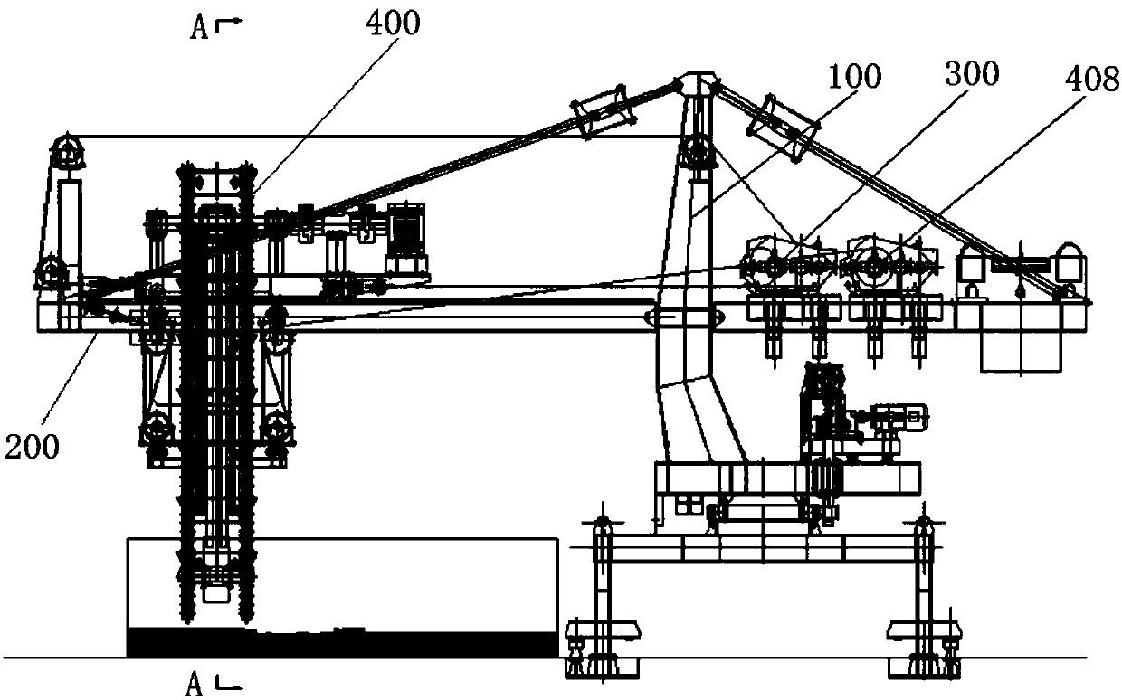
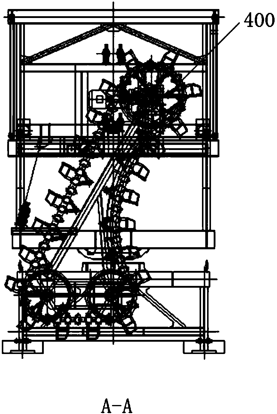
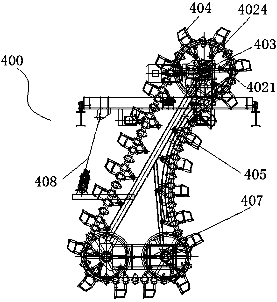
[0033] Such as figure 1 And combine Figure 2 ~ Figure 7 As shown, a chain bucket reclaiming equipment includes: a door frame type equipment support structure 100 configured as a carrying device of the chain bucket reclaiming equipment; a main beam 200 arranged on the equipment support structure 100; a trolley 300, A small frame is arranged on the main beam 200, and the small frame can reciprocate along a track set on the main beam 200; the material reclaiming device 400 passes through the main beam 200 and Vertical to the main beam 200, the reclaiming device 400 is connected to the trolley frame. When the reclaiming position of the reclaiming device 400 needs to be changed, the reclaiming device 400 is pulled by the movement of the trolley 300, Move the reclaiming device 400 to a desired location; for large bulk carriers...


PUM


Abstract

The invention discloses chain bucket obtaining equipment which comprises a door frame type equipment support structure configured to be a bearing device of the chain bucket obtaining equipment, a main beam, a trolley and an obtaining device. The main beam is arranged on the equipment support structure, the trolley is arranged on the main beam through a trolley frame, the trolley frame can reciprocate along a track arranged on the main beam, the obtaining device penetrates through the main beam and is perpendicular to the main beam, and the obtaining device is connected with the trolley frame. When the obtaining position of the obtaining device needs to be changed, the obtaining device is pulled through movement of the trolley, and the obtaining device is moved to the needed position. The invention further discloses a ship unloader. The chain bucket obtaining equipment is large in grabbing amount, low in dead load, high in structural strength, capable of adapting to seagoing vessel continuous ship unloading operation, high in ship unloading efficiency and small in environmental pollution.

Description

Technical field [0001] The invention relates to a reclaiming equipment, in particular to a chain bucket reclaiming equipment and a corresponding ship unloader. Background technique [0002] With the development of the national economy, various ports and terminals have higher and higher requirements for the environmental performance of loading and unloading equipment, and the country is paying more attention to the requirements for energy saving and emission reduction. [0003] In the prior art, bridge-type grab ship unloaders are used for loading and unloading, which are suitable for a wide range of ship types and simple maintenance, but are not environmentally friendly, high cost, high energy consumption, and large terminal construction costs; portal grab ship unloaders have low cost, but Low efficiency and poor environmental protection, basically completely eliminated; L-type chain bucket ship unloader is characterized by good environmental protection and high efficiency. The dis...

Claims


Application Information

Patent Timeline
Patent Type & Authority Patents(China)
IPC IPC(8): B65G67/60B65G35/00B65G65/04
CPCB65G35/00B65G65/04B65G67/606B65G2201/04
Inventor 王悦民胡雄沈莹陈自强余智雄童民慧董凯陈朵朵沈晓阳
Owner SHANGHAI MARITIME UNIVERSITY
Why Eureka
Try Eureka