A diaphragm winding roller

A technology for winding rollers and diaphragms, which is applied in the field of diaphragm winding rollers, can solve problems such as diaphragm release, and achieve the effect of ensuring thickness consistency

Active Publication Date: 2017-12-05
河南天工膜材新能源科技有限公司
View PDF5 Cites 1 Cited by
  • Summary
  • Abstract
  • Description
  • Claims
  • Application Information

AI Technical Summary

Problems solved by technology

[0003] The object of the present invention is to provide a diaphragm winding roller, by using the winding roller, the problem of effectively releasing the internal tension of the diaphragm can be solved

Method used


Image

  • A diaphragm winding roller
  • A diaphragm winding roller
  • A diaphragm winding roller

Examples


Embodiment Construction

[0018] Embodiments of the present invention will be further described below in conjunction with the accompanying drawings.

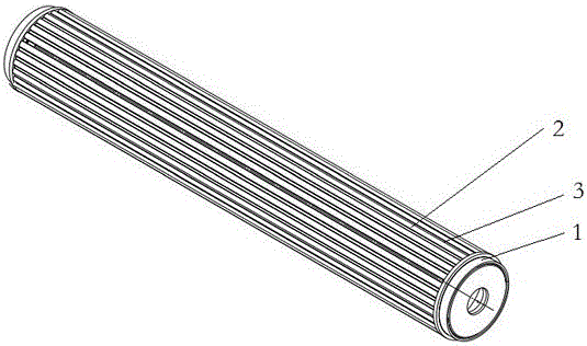
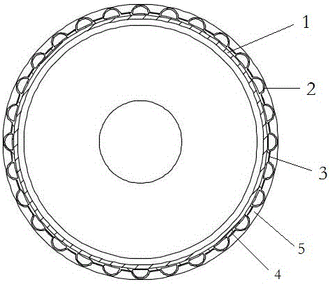
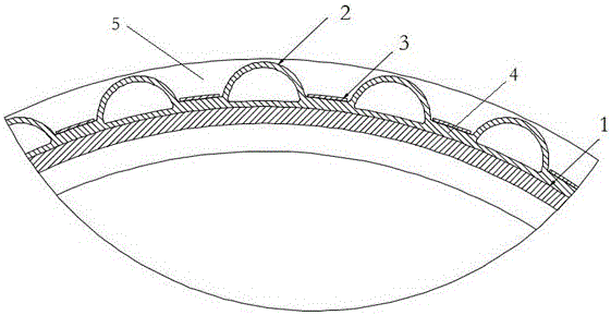
[0019] The specific embodiment of diaphragm winding roller of the present invention, as Figure 1 to Figure 3 As shown, the diaphragm winding roller includes a cylinder body 1, on which a plurality of airbags 2 distributed at intervals are arranged, the airbags 2 are made of rubber with a Shore hardness of 20-30, and have certain flexibility; the airbags 2 is parallel to the axial direction of the cylinder 1, extends to both axial ends of the cylinder 1, and is evenly spaced along the circumference of the cylinder axis.

[0020] The airbag 2 has a D-shaped cross section in the direction perpendicular to the axis of the cylinder, the D-shaped flat side fits the cylinder, the inner cavity of the airbag is filled with air, and the outer surface of the airbag constitutes the outer peripheral surface for winding the diaphragm, that is, the outer surface of th...


PUM


Abstract

The invention provides a membrane rolling roller. The membrane rolling roller comprises a roller body. A plurality of air bags are arranged on the peripheral face of the roller body. Peripheral faces used for rolling a membrane are formed by the outer side faces of the air bags. The air bags communicate with air inflow and outflow openings provided with air valves. By usage of the membrane rolling roller, the problem that tension in the membrane on the rolling roller cannot be smoothly released can be solved.

Description

technical field [0001] The invention relates to a diaphragm winding roller. Background technique [0002] With the rapid development of the battery market, the requirements for the quality of the separator are also increasing. The separator plays an important role in the application of lithium batteries, and the consistency of the thickness of the separator has become a key factor restricting the improvement of the quality of the separator. Through the research on the problem of affecting the thickness of the diaphragm, it is found that the thickness of the diaphragm in the production process is consistent, and after the conventional aging treatment, the yield rate of the diaphragm is much lower than before, so the post-processing process is important for the consistency of the diaphragm thickness. Influence; In the post-processing process, the temperature, stress, gas, etc. inside the diaphragm will be released slowly over time. During the release process, the diaphragm wil...

Claims


Application Information

Patent Timeline
Patent Type & Authority Patents(China)
IPC IPC(8): B65H75/24B65H75/10
CPCB65H75/10B65H75/243
Inventor 潘光和张金辉王珑肖欢焦令宽张晓楠李顺阳王博
Owner 河南天工膜材新能源科技有限公司
Why Eureka
Try Eureka