Working platform leveling device of hydraulic aerial cage

A technology for aerial work vehicles and work platforms, which is applied in the direction of lifting devices, etc., can solve the problems of poor self-weight balance of work buckets, potential safety hazards, and the leveling of work platforms that are only suitable for folding arm type aerial work vehicles, so as to reduce the difficulty of assembly. and production costs, ease of assembly and manufacture, compactness in space

Active Publication Date: 2016-11-09
XUZHOU HANDLER SPECIAL VEHICLE
View PDF8 Cites 17 Cited by
  • Summary
  • Abstract
  • Description
  • Claims
  • Application Information

AI Technical Summary

Problems solved by technology

[0003] Aerial work vehicle is a special vehicle for installation, maintenance and cleaning of high-altitude equipment. Compared with traditional working methods such as scaffolding and ladders, it has the advantages of good work performance, high work efficiency, and safe work. At present, aerial work vehicles are classified according to the type of boom It is usually divided into three categories: folding arm aerial work vehicle, telescopic arm aerial work vehicle and mixed arm form aerial work vehicle composed of two-stage telescopic arm and crank arm. The leveling effect of the aerial work vehicle working platform directly affects the construction The personal safety and operating comfort of personnel, although the existing leveling device of the working platform of the aerial work vehicle can realize the leveling of the working platform, there are still deficiencies
[0004] The Chinese invention patent "leveling mechanism of working bucket of aerial work vehicle" with the application number of 200810061626.8 discloses a leveling mechanism of working bucket of aerial work vehicle. Connecting rods and 1 combined connecting rod realize leveling; among them, 1 balance cylinder is installed at the turntable, lower arm, upper arm and working bucket, 2 single connecting rods and 1 combined connecting rod are arranged between the upper arm and the lower arm, and the upper arm 1. Two single links are set between the working bucket brackets. This method solves the problems of poor self-weight balance, large shaking and poor stability of the working bucket. However, the leveling mechanism has a complex structure and high cost, and is only suitable for two-stage folding arms. Working platform leveling of type aerial work vehicle
[0005] The Chinese utility model patent "Balance Device for Folding Aerial Work Vehicle" with the application number of 200920316691.0 discloses a balance device for a work bucket of a folding aerial work vehicle. The 7 follow-up long and short pull rods and 3 pull rod supports in the frame cooperate with each arm frame to form a parallelogram of variable hinge points to realize platform leveling. It is beautiful and unsafe, but the structure of the leveling mechanism is complicated, and the long pull rod is easy to shake, which has potential safety hazards, and is only suitable for leveling the working platform of the folding arm aerial work vehicle; the application number is 201120571760. The new patent "Aerial Work Vehicle Leveling Device with Anti-Tipping Mechanism" discloses a leveling device for aerial work vehicles with an anti-tipping mechanism, which also has the above shortcomings.
[0006] The Chinese invention patent "Aerial Work Vehicle and Its Working Bucket Leveling Mechanism" with the application number of 201210520175.6 discloses a working bucket leveling mechanism of an aerial work vehicle. The expansion and contraction of the flat oil cylinder further pulls the four-bar linkage mechanism composed of the "V"-shaped curved connecting rod, the straight connecting rod, the connecting rod part of the working bucket mounting frame and a part of the small arm to realize the leveling of the working bucket. This method has a compact structure. , Simple, can make the working bucket rotate relatively smoothly at a large angle relative to the forearm, but the leveling mechanism must be combined with the control device of the aerial work vehicle to be applied, so the cost is high, and the control device is performing signal conversion and sending There is a time lag and inaccurate action between the execution of the command and the execution of the leveling cylinder, resulting in large leveling errors and poor results

Method used


Image

  • Working platform leveling device of hydraulic aerial cage
  • Working platform leveling device of hydraulic aerial cage
  • Working platform leveling device of hydraulic aerial cage

Examples


Embodiment Construction

[0026] The present invention will be further described below in conjunction with the accompanying drawings (hereinafter, the normal driving direction of the aerial work vehicle is described as the front).

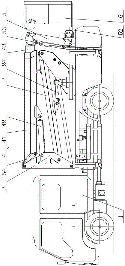
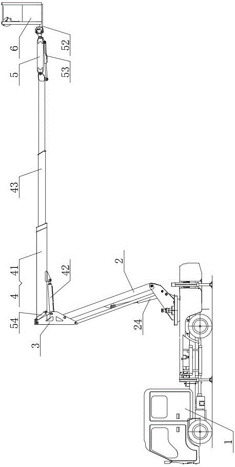
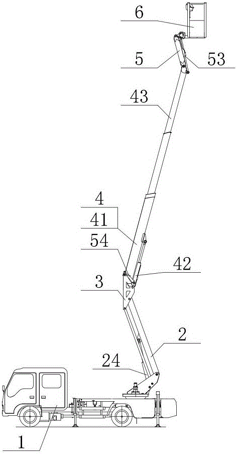
[0027] Such as Figure 4 As shown, the working platform leveling device 5 of the aerial work vehicle includes a connecting rod crank arm 51 , a bracket 52 , a crank arm luffing cylinder 53 , a primary leveling hydraulic cylinder 54 and a secondary leveling hydraulic cylinder 55 .

[0028]The link type crank arm 51 includes a first connecting frame 511, a first pull rod 512, a second pull rod 513 and a second connecting frame 514; the first connecting frame 511 is provided with four hinges of B, C, D and E Points, hinge points B, D, E are arranged around the hinge point C around the hinge point C, and the link type crank arm 51 is hingedly connected to the end section of the telescopic arm or the folding arm through the hinge point C as a whole; the second connecting frame 5...


PUM


Abstract

The invention discloses a working platform leveling device of a hydraulic aerial cage. The working platform leveling device comprises a link-type crank arm, a bracket, a crank arm derricking cylinder, a primary leveling hydraulic cylinder and a secondary leveling hydraulic cylinder, wherein the link-type crank arm comprises a first link span, a first pull rod, a second pull rod and a second link span; a first pull rod and a second pull rod in a left-right direction are parallelly and respectively articulated with the first link span and the second link span in a staggered manner; and hinge joints B, C, G and F jointly define a first four-link mechanism, hinge joints C, D, H and G jointly define a second four-link mechanism, and the shared hinge joints C and G of the two four-link mechanisms entirely constitute a double-parallel four-link mechanism. The working platform leveling device of the hydraulic aerial cage is capable of realizing rotation (greater than 180 degrees) without dead points of the link-type crank arm, is large in operation range, high in flexibility, simple and compact in structure and low in manufacturing cost, has the advantages of beautiful appearance, reverse inclination prevention capability, anti-seizing capability and large operation range, and is applicable to various hydraulic aerial cages.

Description

technical field [0001] The invention relates to a working platform leveling device, in particular to a working platform leveling device suitable for high-altitude operation vehicles, and belongs to the technical field of special vehicles. Background technique [0002] With the rapid development of my country's economy and the rapid increase of vehicle traffic flow, the number of overpasses, ring viaducts and mountain tunnels, river tunnels or lake tunnels in the city is increasing day by day. A large amount of dust rolled up by driving vehicles is mixed together and finally attached to the walls, sound insulation screens and guardrails of overpasses, viaducts and tunnels. Over time, obvious stains are formed. The stains will not only affect the appearance, but also affect the lighting effect. Serious It even affects the driver's line of sight and thus affects driving safety. Usually, it is necessary to regularly clean and maintain the walls, sound insulation screens and guardr...

Claims


Application Information

Patent Timeline
Patent Type & Authority Applications(China)
IPC IPC(8): B66F11/04
CPCB66F11/046
Inventor 王然然樊传岗朱赛李培启耿艳杰
Owner XUZHOU HANDLER SPECIAL VEHICLE
Why Eureka
Try Eureka