Quenching device of shaft lever

A technology of quenching device and shaft, which is applied in the field of quenching, can solve the problems of low quenching efficiency and high cost of shaft quenching, and achieve the effects of simple structure, convenient operation, and reduced input cost

Inactive Publication Date: 2016-11-09
NEXTEER LINGYUN DRIVELINE WUHU
View PDF7 Cites 10 Cited by
  • Summary
  • Abstract
  • Description
  • Claims
  • Application Information

AI Technical Summary

Problems solved by technology

[0003] Aiming at the deficiencies of the prior art, the present invention provides a shaft quenching device, which improves the quenching efficiency of the shaft by providing a manipulator to transfer the shaft, so as to solve the problems of low quenching efficiency and high cost of the existing shaft

Method used


Image

  • Quenching device of shaft lever

Examples


Embodiment Construction

[0011] In order to deepen the understanding of the present invention, the present invention will be further described below in conjunction with the examples, which are only used to explain the present invention, and do not constitute a limitation to the protection scope of the present invention.

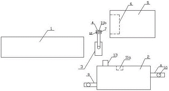
[0012] Such as figure 1 As shown, this embodiment provides a shaft quenching device, including a conveyor belt 1 for transporting shafts and a cooling pool 2, the cooling pool 2 is installed on one side of the conveyor belt 1, and the cooling pool 2 is connected to the The middle of conveyor belt 1 is provided with manipulator 3, and described manipulator 3 is provided with the fixture 4 that grabs axle rod usefulness, and described cooling pool 2 is also provided with quenching furnace 5, is provided with in described quenching furnace 5 The tooling plate 6 is provided with a position sensor 7 on the fixture 4 . The cooling pool 2 is provided with a water inlet pipe 8 and a water o...


PUM


Abstract

The invention discloses a quenching device of a shaft lever. The quenching device comprises a conveying belt and a cooling pond, wherein the conveying belt is used for conveying the shaft lever, the cooling pond is installed on one side of the conveying belt, a manipulator is arranged between the cooling pond and the conveying belt, a fixture which is used for grabbing the shaft lever is arranged on the manipulator, a quenching furnace is further arranged on one side of the cooling pond, a tooling plate is arranged in the quenching furnace, and a position sensor is arranged on the fixture. The manipulator is arranged to transfer the shaft lever, so that the quenching efficiency of the shaft lever is improved. The quenching device has the advantages of simple structure and convenience in operation, the quenching effect is greatly increased, and the input cost is reduced.

Description

technical field [0001] The invention relates to the technical field of quenching, in particular to a quenching device for an automobile front drive shaft. Background technique [0002] The shaft is an important transmission part in the front drive system of the automobile. In the production of the shaft, there is usually a quenching process to improve its overall performance. The traditional quenching of the shaft is not easy to control, difficult to operate, and high in cost. The quenching effect is not ideal enough, therefore, it is particularly important to solve this kind of problems. Contents of the invention [0003] Aiming at the deficiencies of the prior art, the present invention provides a shaft quenching device, which improves the quenching efficiency of the shaft by providing a manipulator to transfer the shaft, so as to solve the problems of low quenching efficiency and high cost of the existing shaft. [0004] In order to solve the above problems, the presen...

Claims


Application Information

Patent Timeline
Patent Type & Authority Applications(China)
IPC IPC(8): C21D1/63C21D9/28
CPCC21D1/63C21D9/0062C21D9/28
Inventor 左树东周松张长悦
Owner NEXTEER LINGYUN DRIVELINE WUHU
Why Eureka
Try Eureka