
Vacuum multi-purpose furnace

A multi-purpose furnace and vacuum technology, applied in coating, quenching device, metal material coating process, etc., can solve problems such as inability to feed materials, poor continuity and automation, and low heat treatment efficiency

Active Publication Date: 2016-11-09
扬州市金盛热处理有限公司
View PDF6 Cites 6 Cited by
  • Summary
  • Abstract
  • Description
  • Claims
  • Application Information

AI Technical Summary

Problems solved by technology

[0002] In the prior art, the vacuum furnace includes a furnace shell, and the furnace shell is equipped with an inlet and outlet rail. The workpiece cannot be fed during heat treatment. The workpiece must be taken out after the heat treatment is completed and the workpiece is cooled. The material tray with the workpiece is pushed to the heat treatment station along the feeding and discharging track, the vacuum furnace can only realize one heat treatment process, the work continuity and automation are poor, and the heat treatment efficiency is low

Method used


Image

  • Vacuum multi-purpose furnace
  • Vacuum multi-purpose furnace
  • Vacuum multi-purpose furnace

Examples


Embodiment Construction

[0026] The following will be described in detail in conjunction with specific implementation methods.

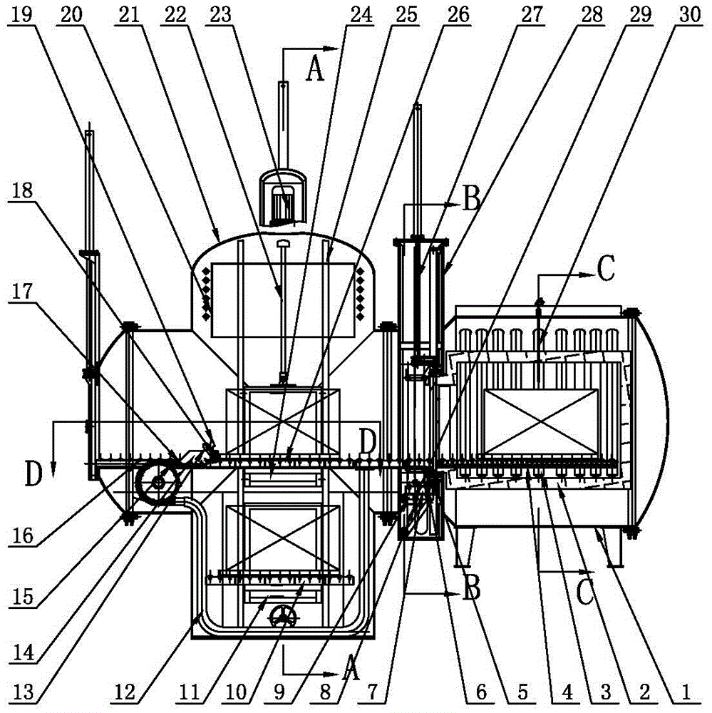
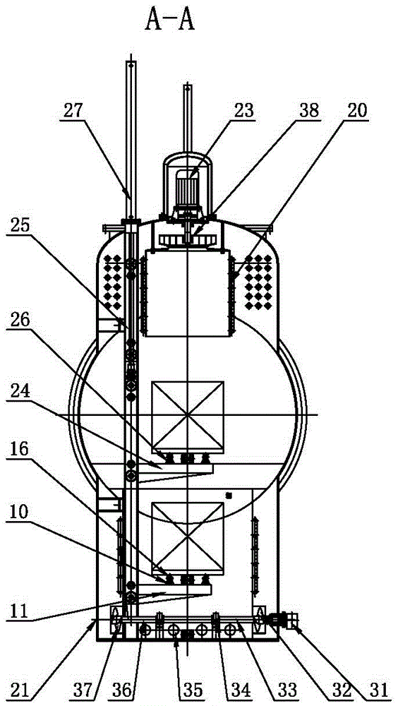
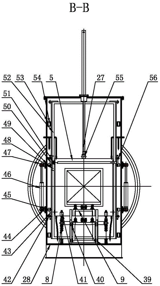
[0027] like Figure 1 to Figure 10A vacuum multipurpose furnace shown includes a quenching furnace shell 21, an inner furnace shell 28 and a carburizing furnace shell 1. The quenching furnace shell 21 is connected to the carburizing furnace shell 1 through the inner furnace shell 28, and the opening of the quenching furnace shell 21 An outer furnace door is provided, and both the quenching furnace shell 21 and the carburizing furnace shell 1 are provided with an inlet and outlet rail 4, and the quenching furnace shell 21 is provided with a wind guide hood 20, a push-pull feeder and a lifting platform for feeding and discharging materials, push-pull The feeder and the lifting platform are in a cross shape. The push-pull feeder includes a second motor 31 and a first chain box 12. The second motor 31 is connected to a sprocket 70 in transmission, and the sprocket 70 is connecte...


PUM


Abstract

The invention provides a vacuum multi-purpose furnace, which belongs to the technical field of heat treatment. The vacuum multi-purpose furnace comprises a quenching furnace shell, an inner furnace shell and a carburizing furnace shell, wherein the quenching furnace shell is connected with the carburizing furnace shell by virtue of the inner furnace shell, an outer furnace door is arranged at an opening of the quenching furnace shell, material inlet and outlet tracks are arranged in the quenching furnace shell and the carburizing furnace shell, a push-pull machine and a lifting platform which are used for feeding and discharging materials are arranged in the quenching furnace shell, the push-pull machine and the lifting platform are crossed, a first motor is arranged on the top of the quenching furnace shell, the first motor is connected with a fan, a lifting inner furnace door, a door frame, a compensation track assembly and a pressing assembly are arranged in the inner furnace shell, the door frame can be pressed on the inner furnace shell by the pressing assembly, the inner furnace door can move along the door frame, the compensation track assembly is lifted along with the inner furnace door, a heater is arranged at the bottom of the quenching furnace shell, an internal furnace is arranged in the carburizing furnace shell, a plurality of electric radiation heating pipes are arranged in the carburizing furnace shell, and vacuum nitrogen charging units are respectively connected to the quenching furnace shell and the carburizing furnace shell. The vacuum multi-purpose furnace has the advantage of high degree of automation, and the efficiency of heat treatment is improved.

Description

technical field [0001] The invention relates to a heat treatment furnace, in particular to a vacuum furnace. Background technique [0002] In the prior art, the vacuum furnace includes a furnace shell, and the furnace shell is equipped with an inlet and outlet track. The workpiece cannot be fed during heat treatment. The workpiece must be taken out after the heat treatment is completed and the workpiece is cooled. The material tray with the workpiece is pushed to the heat treatment station along the feeding and discharging track. The vacuum furnace can only realize one heat treatment process, the continuity and automation of the work are poor, and the heat treatment efficiency is low. Contents of the invention [0003] Aiming at the defects in the prior art, the purpose of the present invention is to overcome the deficiencies in the above-mentioned prior art, and provide a vacuum multi-purpose furnace, which integrates multi-functional work, can also feed materials during ...

Claims


Application Information

Patent Timeline
Patent Type & Authority Applications(China)
IPC IPC(8): C21D1/773C21D1/62C23C8/22
CPCC21D1/62C21D1/773C23C8/22
Inventor 杭辉
Owner 扬州市金盛热处理有限公司
Learn More