
Fluidization scouring promotion device based on silt flowing deformation

A sediment and fluidization technology, applied in river regulation, water conservancy engineering, sea area engineering, etc., can solve problems such as difficulty in controlling dredging position and dredging depth, inability to directly shear soil, and difficulty in achieving good results. , to achieve the effect of controllable scope of action, controllable dredging depth, and controllable dredging position

Active Publication Date: 2016-11-09
SHANGHAI JIAO TONG UNIV
View PDF8 Cites 1 Cited by
  • Summary
  • Abstract
  • Description
  • Claims
  • Application Information

AI Technical Summary

Problems solved by technology

Its main disadvantages are: 1) It cannot move the highly viscous sediment, and it cannot achieve good results when dealing with fine-grained viscous silt. 2) The device has poor flexibility, and it is difficult to control the dredging position and dredging depth
Its shortcomings mainly lie in: 1) when dealing with highly consolidated viscous sediment, because the sediment strength is too high, the method of high-pressure water scouring is difficult to obtain good results; 2) the energy utilization rate of high-pressure water scouring is low, Its energy cannot directly act on the shearing soil, and the energy loss is large; 3) High-pressure water washing will cause a large amount of sediment to be suspended, causing environmental pollution

Method used


Image

  • Fluidization scouring promotion device based on silt flowing deformation
  • Fluidization scouring promotion device based on silt flowing deformation

Examples


Embodiment 1

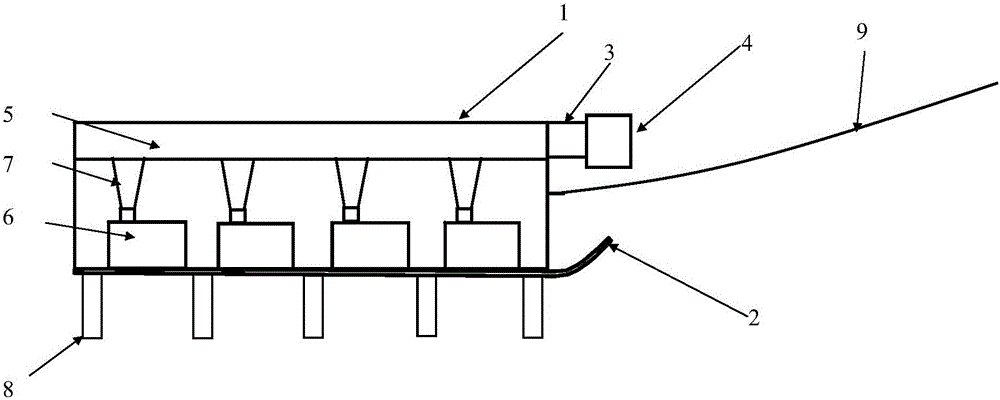
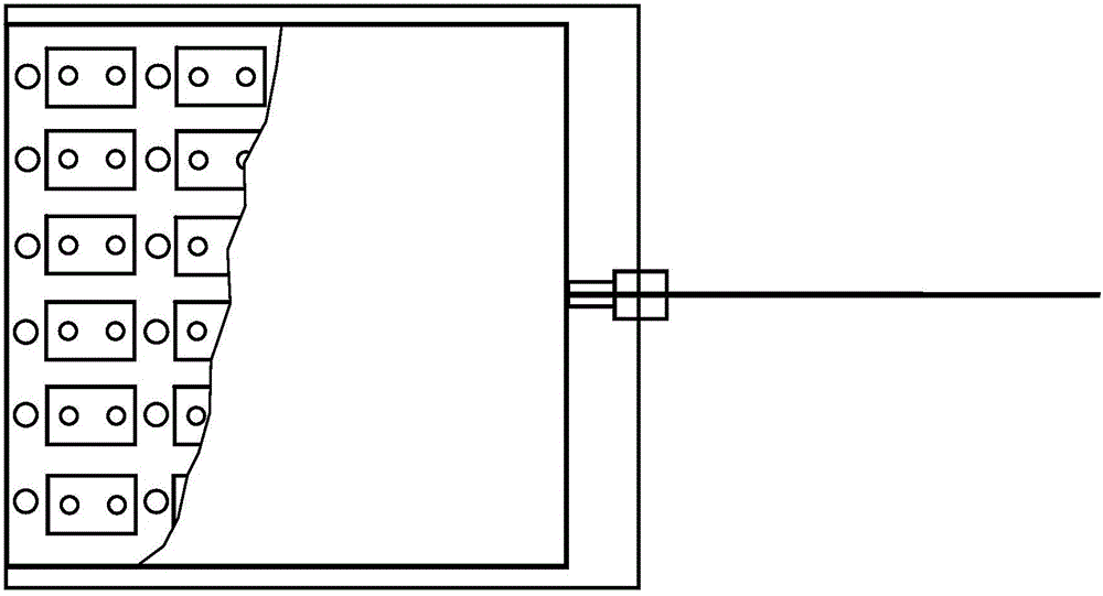
[0030] like Figure 1-2 As shown, this embodiment provides a fluidization boosting device supported by a hydraulic vibrator, which consists of a housing 1, a mud skid 2, an inlet pipe 3, a damping joint 4, a flow supply chamber 5, and a vibration unit 6 , a diversion tube 7, a supplementary flow column 8 and a tow cable 9, wherein: the housing 1 is arranged on the mud skid 2, the upper part of the housing 1 is opened to communicate with the inlet pipe 3, and the bottom of the housing 1 is opened There are several holes in communication with the supplementary flow column 8; the inlet pipe 3 is arranged on the side wall of the front end of the housing 1, and the upper end of the inlet pipe 3 is connected to the damping joint 4; The front end of 5 communicates with the inlet pipe 3, and the lower part of the flow supply chamber 5 communicates with a plurality of guide tubes 7; the vibration unit 6 is arranged at the bottom of the housing 1, and the upper inlet of the vibration un...

Embodiment 2

[0043] Such as Figure 1-2 As shown, this embodiment provides a fluidization boosting device supported by a pneumatic vibrator, which consists of a housing 1, a mud skid 2, an inlet pipe 3, a damping joint 4, a flow chamber 5, a vibration unit 6, The diversion tube 7, the supplementary flow post 8 and the tow cable 9 are composed, wherein: the housing 1 is arranged on the mud skid 2, and the upper opening of the housing 1 communicates with the inlet pipe 3, and several openings are opened at the bottom of the housing 1. The hole communicates with the supplementary flow column 8; the inlet pipe 3 is arranged on the front side wall of the housing 1, and the upper end of the inlet pipe 3 is connected to the damping joint 4; The front end of the front end communicates with the inlet pipe 3, and the lower part of the flow supply chamber 5 communicates with a plurality of guide tubes 7; the vibration unit 6 is arranged at the bottom of the housing 1, and the upper inlet of the vibra...


PUM


Abstract

The invention provides a fluidization scouring promotion device based on silt flowing deformation. The fluidization scouring promotion device comprises a shell, a bearing component, a flow inlet component, a damping connecting piece, a flow supply component, a vibration unit, a guiding component and a flow supplement component. The shell is arranged on the bearing component. Holes communicating with the flow inlet component are formed in the upper portion of the shell. A plurality of holes used for communicating with the flow supplement component are formed in the bottom of the shell. The flow inlet component is arranged on the side wall at the front end of the shell. The upper end of the flow inlet component is connected with the damping connecting piece. The flow supply component is arranged on the upper portion of the interior of the shell. The front end of the flow supply component communicates with the flow inlet component. The bottom of the flow supply component communicates with the guiding component. The vibration unit is arranged at the bottom of the shell. A flow inlet is formed in the upper portion of the vibration unit and used for communicating with the guiding component. The flow supplement component is arranged at the bottom of the bearing component. The fluidization scouring promotion device is integrated, is easy to mount and dismount, can be used repeatedly in different areas to be disposed and is easy to operate and safe in construction, and the fluidization scouring promotion device is widely applied to desilting work of reservoirs, harbour basins, channels and the like.

Description

technical field [0001] The invention relates to the technical field of water conservancy engineering and water environment protection engineering, in particular to a fluidization acceleration device based on sediment rheology. Background technique [0002] According to the 2013 census, there are more than 98,000 reservoirs with a storage capacity of 100,000 cubic meters or more in my country. There are about 756 large reservoirs with a total storage capacity of 749.985 billion m 3 , accounting for 80.45% of the total storage capacity of national reservoirs. There are 4,938 medium-sized reservoirs with a total storage capacity of 111.976 billion m 3 ; There are 93,308 small reservoirs with a total storage capacity of 70.351 billion m 3 . [0003] The problem of sedimentation in global reservoirs is quite serious. According to statistics, the annual loss rate of reservoir capacity due to sedimentation is about 1% globally, equivalent to 50 billion m 3 The annual storage ...

Claims


Application Information

Patent Timeline
Patent Type & Authority Applications(China)
IPC IPC(8): E02B3/02
CPCE02B3/023
Inventor 喻国良张民曦王闻恺
Owner SHANGHAI JIAO TONG UNIV
Learn More