
Water shield arrival receiving structure and receiving method

A technology for receiving structures and shield machines, which is applied in earth-moving drilling, mining equipment, tunnels, etc., can solve the problems of long dismantling time, high amortization cost of tunnel equipment, and low work efficiency of dismantling machines in the tunnel, so as to save engineering. effect of investment

Active Publication Date: 2016-11-09
CHINA RAILWAY SIYUAN SURVEY & DESIGN GRP
View PDF6 Cites 7 Cited by
  • Summary
  • Abstract
  • Description
  • Claims
  • Application Information

AI Technical Summary

Problems solved by technology

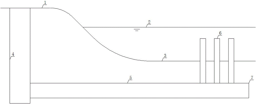
[0004] 1) When adopting the scheme of dismantling the shield in the tunnel, the shield machine needs to be dismantled into parts and transported out of the tunnel, and the cutter head, front shield and shield shell remain permanently at the bottom of the water, the residual value of the shield machine is low, and the removal (row) Water tunnels are generally not very long, resulting in high equipment amortization costs for such tunnels;
[0005] 2) When the shield tunnel dismantling scheme is adopted, the work efficiency of the tunnel dismantling machine is low, the dismantling time is long, and the shield dismantling work cannot be carried out in parallel with other processes in the tunnel, resulting in a long total construction period;
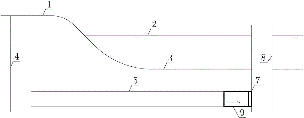
[0006] 3), adopt the scheme of setting receiving work well in water (refer to figure 2 ), it is necessary to ensure that there is no water in the well. The construction of the receiving work well in water is difficult and the project cost is high;

Method used


Image

  • Water shield arrival receiving structure and receiving method
  • Water shield arrival receiving structure and receiving method
  • Water shield arrival receiving structure and receiving method

Examples


Embodiment Construction

[0032] In order to make the object, technical solution and advantages of the present invention clearer, the present invention will be further described in detail below in conjunction with the accompanying drawings and embodiments. It should be understood that the specific embodiments described here are only used to explain the present invention, not to limit the present invention. In addition, the technical features involved in the various embodiments of the present invention described below can be combined with each other as long as they do not constitute a conflict with each other.

[0033] refer to image 3 , an underwater shield machine arrival receiving structure, including a shield originating shaft 4, a shield tunnel design and use section 5, a temporary climbing section 11 of a shield tunnel and a temporary operation platform 14, wherein,

[0034] The shield launching shaft 4 is used as the initial part of the shield machine's excavation and excavation, which is arran...


PUM


Abstract

The invention belongs to the field of shield tunnels, and discloses a water shield arrival receiving structure and a receiving method. The water shield arrival receiving structure comprises a shield starting well, a shield tunnel design use section, a shield tunnel temporary climbing section and a temporary operation platform. The receiving method comprises the following steps of (1) enabling a shield to start from the shield starting well; after the shield passes through the shield tunnel design use section, reaching the terminal of the shield tunnel design use section; (2) after the shield reaches the terminal of the shield tunnel design use section, enabling the shield to upwards tunnel along the shield tunnel temporary climbing section until to the temporary operation platform; (3) after the shield reaches the temporary operation platform, disassembling, transporting, and completing the shield receiving process; (4) arranging a transverse blocking wall at the shield tunnel design terminal, disassembling or backfilling the temporary operation platform and the tunnel temporary climbing section. The shield tunnel design use section and receiving method have the advantages that the temporary operation platform is filled and built at the water area in front of the terminal of the shield tunnel design use section, and the shield receiving process is completed on the temporary operation platform; the safety is realized in the water shield receiving process, and the efficiency is high.

Description

technical field [0001] The invention belongs to the field of shield tunnels, and more specifically relates to an underwater shield machine arrival receiving structure. Background technique [0002] With the development of thermal power plants and nuclear power plants, more and more water intake and drainage tunnels need to be built. Most of these water intake and drainage tunnels are located below the water surface at one end, connected to the water body through a vertical water intake or outfall, and the other end is located on the bank where water is used. [0003] refer to figure 1 , The construction of this kind of water intake and drainage tunnels starts from the working well on the bank slope and excavates into the water. After the shield machine reaches the design position, it generally adopts the scheme of dismantling in the cave or setting up a receiving working well in the water and lifting it out. The following problems exist when the water intake (drainage) shi...

Claims


Application Information

Patent Timeline
Patent Type & Authority Applications(China)
IPC IPC(8): E21D9/06E21D9/12E21D9/14
CPCE21D9/06E21D9/122E21D9/14
Inventor 肖明清邓朝辉龙凡鲁志鹏孙峰
Owner CHINA RAILWAY SIYUAN SURVEY & DESIGN GRP
Learn More