Eureka AIR delivers breakthrough ideas for toughest innovation challenges, trusted by R&D personnel around the world.

Air-concentrating power generation station

A power station and wind gathering technology, which is applied to wind power generation, wind turbines, and wind turbines consistent with the wind direction. The effect of less land

Inactive Publication Date: 2016-11-09
黄宝文
View PDF5 Cites 3 Cited by
  • Summary
  • Abstract
  • Description
  • Claims
  • Application Information

AI Technical Summary

Problems solved by technology

[0004] The purpose of the present invention is to overcome the defects of the flat-axis fan or the vertical-axis fan and the existing wind-gathering power generation device with less wind energy capture and low utilization rate, and provide a wind-gathering power generation device that can capture wind energy to the greatest extent and improve the utilization rate of wind energy

Method used


Image

  • Air-concentrating power generation station
  • Air-concentrating power generation station
  • Air-concentrating power generation station

Examples


Embodiment Construction

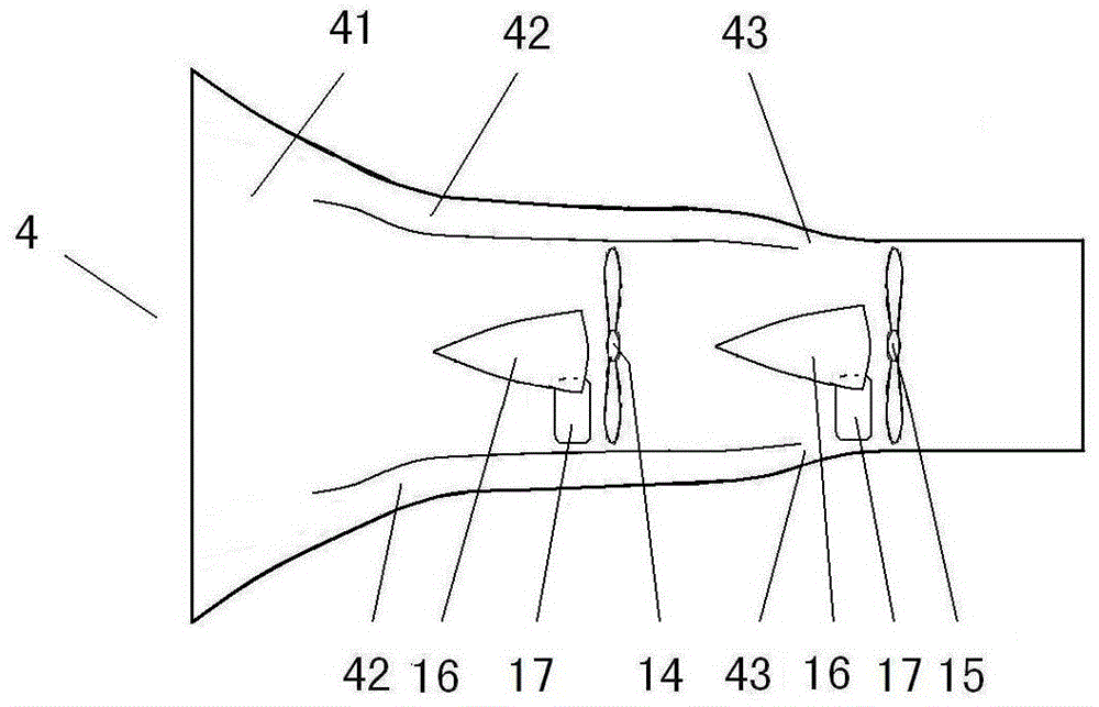
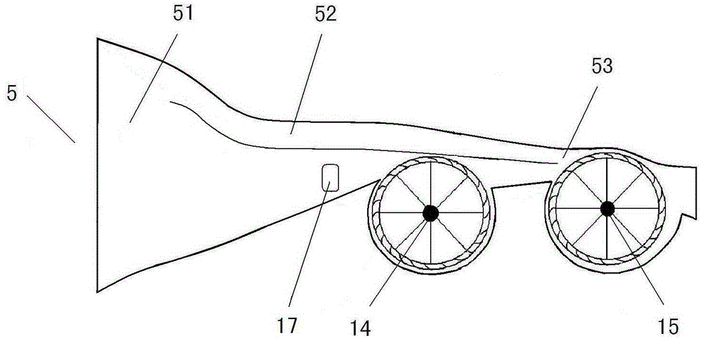
[0013] figure 1 figure 2 Among them, one end of the first air gathering tube 4 is the bell mouth 41, and one end of the second air gathering tube 5 is the bell mouth 51; The part is a double-layer structure, and the interval in the double-layer constitutes the air inlet channel 42 of the first air collector and the air inlet channel 52 of the second air collector; A blower fan 14 and the second blower fan 15 two blowers, the first air gathering tube air inlet channel air outlet 43 and the second air gathering tube air inlet channel air outlet 53 are located before the blades of the second blower fan 15, and the air inlet makes the first After the first fan 14 rotates to generate electricity, the wind energy surplus will not be lost due to the seal of the cylinder body, and the wind that can be imported into the corresponding air outlet makes the second fan 15 rotate to generate electricity.

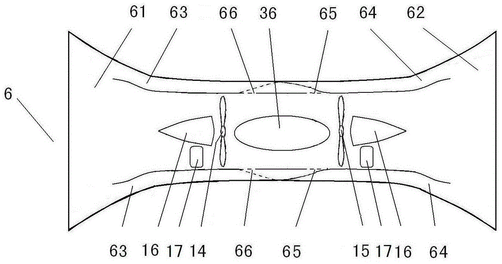
[0014] image 3 Among them, the first bell mouth 61 and the second bell mouth 62 ...


PUM


Abstract

The invention discloses an air-concentrating power generation station. According to the air-concentrating power generation station, at least two fans are installed in each air-concentrating barrel, each fan is correspondingly provided with an air inlet channel, the remainder of air energy of rotation power generation of the front fan cannot be dissipated and wasted because a sealed barrel body is arranged due to air inlet of a horn mouth, and can be merged with air in another air inlet channel for enabling the rear fan to rotate for power generation. The air-concentrating barrels are fixedly arranged on a frame structure in parallel or in an overlapping manner to form a power generation dam, all air energy in the area of the power generation dam can be captured and utilized, and the air energy of an air field is furthest utilized, thus the installed capacity and power generation capacity of the air field are furthest increased.

Description

technical field [0001] The invention relates to technical equipment for wind power generation, in particular to a wind gathering power station. Background technique [0002] Existing wind farms are generally equipped with flat-axis fans or vertical-axis fans to generate electricity, and a large distance should be left between adjacent fans, which will waste a lot of wind energy in the wind farm; the wind energy in the swept area of ​​the wind blades cannot be fully utilized, and the Less than half of the captured wind energy is utilized, and the residual wind energy after the wind turbine is utilized is not only basically lost, but also often causes turbulent wind, which affects the use of wind energy by adjacent wind turbines. Therefore, the existing wind farm occupies a large area, but the wind capture area is small, and the utilization rate of wind energy is low; the wind farm construction investment is large, but the installed capacity and power generation are small. ...

Claims


Application Information

Patent Timeline
Patent Type & Authority Applications(China)
IPC IPC(8): F03D1/04F03D3/04
CPCF03D1/04F03D3/04Y02E10/72Y02E10/74
Inventor 黄宝文黄郑隽
Owner 黄宝文
Why Eureka
Eureka Blog
Learn More