Protection circuit, method and device for compressor

A compressor protection and circuit protection technology, applied in the field of compressor control, can solve problems such as low reliability

Active Publication Date: 2016-11-09
GREE ELECTRIC APPLIANCES INC
View PDF6 Cites 1 Cited by
  • Summary
  • Abstract
  • Description
  • Claims
  • Application Information

AI Technical Summary

Problems solved by technology

[0005] The embodiment of the present invention provides a compressor protection circuit, method and device to

Method used


Image

  • Protection circuit, method and device for compressor
  • Protection circuit, method and device for compressor
  • Protection circuit, method and device for compressor

Examples


Embodiment 1

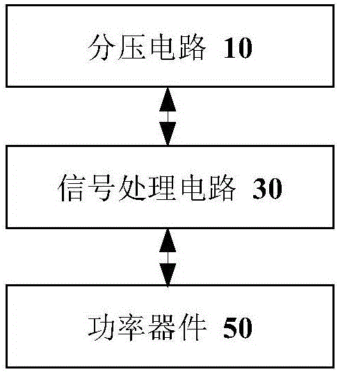
[0025] figure 1 is a schematic diagram of a compressor protection circuit according to an embodiment of the present invention, such as figure 1 As shown, the protection circuit can include:

[0026] The voltage divider circuit 10 is provided with a temperature control switch in the voltage divider circuit, and the voltage divider circuit is used to output a voltage signal in response to the action of the temperature control switch, wherein the temperature control switch operates based on the cylinder temperature of the compressor;

[0027] The signal processing circuit 30 is connected to the voltage dividing circuit, and is used to use the voltage signal output by the voltage dividing circuit as a reference voltage signal, and output a control signal based on a comparison result between the reference voltage signal and the comparison voltage signal;

[0028] The power device 50 is connected with the signal processing circuit and used for controlling the working state of the c...

Embodiment 2

[0060] According to an embodiment of the present invention, an embodiment of a compressor protection method is provided. It should be noted that the steps shown in the flow chart of the accompanying drawings can be executed in a computer system such as a set of computer-executable instructions, and, Although a logical order is shown in the flowcharts, in some cases the steps shown or described may be performed in an order different from that shown or described herein.

[0061] Figure 4 is a flowchart of a compressor protection method according to an embodiment of the present invention, such as Figure 4 As shown, the method includes the following steps:

[0062] Step S402, the voltage dividing circuit outputs a reference voltage signal to the signal processing circuit in response to the action of the temperature control switch, wherein the temperature control switch operates based on the cylinder temperature of the compressor;

[0063] Step S404, the signal processing circu...

Embodiment 3

[0078] Figure 5 is a schematic diagram of a compressor protection device according to an embodiment of the present invention, such as Figure 5 As shown, the protection device may include: a first output module 51 , a second output module 53 and a control module 55 .

[0079] Wherein, the first output module 51 is configured to output a reference voltage signal to the signal processing circuit in response to the action of the temperature control switch through the voltage divider circuit, wherein the temperature control switch operates based on the cylinder temperature of the compressor;

[0080] The second output module 53 is configured to output the control signal to the power device through the signal processing circuit based on the reference voltage signal;

[0081] The control module 55 is used to control the working state of the compressor under the trigger of the control signal through the power device.

[0082] According to the embodiment of the present invention, t...


PUM


Abstract

The invention discloses a protection circuit, method and device for a compressor. The protection circuit comprises a voltage division circuit, a signal processing circuit and a power device, wherein a temperature control switch is arranged in the voltage division circuit which is used for outputting voltage signals according to actions of the temperature control switch, and the temperature control switch acts on the basis of the temperature of a cylinder of the compressor; the signal processing circuit is connected with the voltage division circuit and used for outputting control signals on the basis of comparison results of reference voltage signals, namely the voltage signals output by the voltage division circuit, and comparison voltage signals; and the power device is connected with the signal processing circuit and used for controlling work states of the compressor on the basis of the control signals. By means of the protection circuit, method and device for the compressor, the technical problem of low reliability of an existing compressor overheat protection scheme is solved.

Description

technical field [0001] The invention relates to the field of compressor control, in particular to a compressor protection circuit, method and device. Background technique [0002] Existing compressor overheat protection is realized through a normally closed temperature control switch. Specifically, the temperature of the compressor cylinder is detected through the normally closed temperature control switch. When the temperature of the compressor cylinder reaches the preset value of the normally closed temperature control switch When the action limit is reached, the normally closed temperature control switch changes from the closed state to the open circuit state, and then the change signal corresponding to the state change of the normally closed temperature control switch is transmitted to the Micro Control Unit (MCU), and the MCU detects the change The signal indicates that the compressor is overheated, and the change signal is the overheating signal of the compressor. Afte...

Claims


Application Information

Patent Timeline
IPC IPC(8): F04B49/10F04B49/06H02H5/04
CPCF04B49/06F04B49/10H02H5/04F04B49/065F04B2201/0801H02H5/047
Inventor 陈名才庞伟
Owner GREE ELECTRIC APPLIANCES INC
Why Eureka
Try Eureka