
A two-stage gas pressure reducing valve

A pressure reducing valve and gas technology, applied in safety valves, balance valves, valve devices, etc., can solve the problems of outlet pressure accuracy and stability manufacturing accuracy, etc., and achieve stable sealing, high control accuracy, and stable pressure Effect

Inactive Publication Date: 2018-02-23
CHANGDE XIANGYU EQUIP MFG
View PDF7 Cites 0 Cited by
  • Summary
  • Abstract
  • Description
  • Claims
  • Application Information

AI Technical Summary

Problems solved by technology

Although the single-stage pressure reducing valve has the function of reducing and stabilizing the pressure, the accuracy and stability of the outlet pressure are greatly affected by the disturbance of the inlet pressure and the manufacturing accuracy of the pressure regulating spring.
Therefore, for the occasions with high outlet pressure control accuracy, stable pressure and good dynamic characteristics, single-stage typical gas pressure reducing valves cannot meet the requirements.

Method used


Image

  • A two-stage gas pressure reducing valve
  • A two-stage gas pressure reducing valve
  • A two-stage gas pressure reducing valve

Examples


Embodiment Construction

[0023] Below in conjunction with accompanying drawing, the technical scheme of the patent of the present invention is described further.

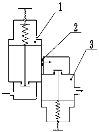
[0024] exist figure 1 Middle: The first-stage pressure reducing valve 1 on the left is installed upright, and the second-stage pressure-reducing valve 3 on the right is reverse-installed.

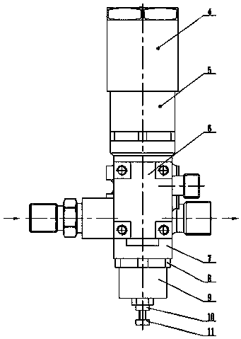
[0025] exist figure 2 Middle: High-pressure gas flows in from the lower end of the primary valve body 6 on the left, and flows out from the middle of the secondary valve body 7 on the right after two times of decompression and pressure stabilization. The outlet diameter is larger than the inlet diameter.

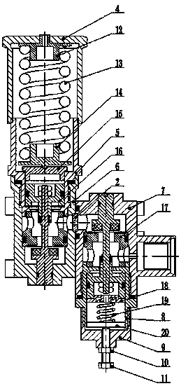
[0026] exist image 3 Middle: The valve assembly 16 and the throttle valve seat 17 are installed in the cavity of the primary valve body 6, the upper end is connected with the primary valve cover 5, the upper end of the primary valve cover 5 is connected with the primary adjusting nut 4, the upper cavity of the primary valve cover 5 is connected wit...


PUM


Abstract

A two-stage gas pressure reducing valve is composed of two pressure reducing valves. A primary pressure reducing valve on the left side is positively installed, a secondary pressure reducing valve on the right side is inversely installed, an inlet of the secondary pressure reducing valve is connected with an outlet of the primary pressure reducing valve, and a throttle orifice is arranged between the secondary pressure reducing valve and the primary pressure reducing valve. After high-pressure gas undergoes pressure reduction and pressure stabilization through the primary pressure reducing valve, medium-pressure gas having a certain value is obtained; the medium-pressure gas enters the secondary pressure reducing valve through the throttle orifice, and the secondary pressure reducing valve continues to perform pressure reduction and pressure stabilization on the medium-pressure gas, so that the medium-pressure gas enters the secondary pressure reducing valve through the throttle orifice, so as to meet the requirements of a gas pipe system. Compared with the prior art, the two-stage gas pressure reducing valve has the remarkably advantages that 1) outlet pressure control accuracy is high, the pressure is stable, dynamic characteristics are good, pressure regulating amplitude is high, and the pressure reduction effect is obvious; 2) during the pressure regulation, a sensitive element and a throttle valve core react simultaneously, and the reaction aftereffect is reduced, so that the pressure regulating response is quicker and more accurate.

Description

technical field [0001] The invention relates to the field of gas pressure reducing valves, in particular to a two-stage gas pressure reducing valve. Background technique [0002] The gas pressure reducing valve is a kind of flow velocity and kinetic energy of the medium particles that change the flow rate and kinetic energy of the medium particle by changing the throttle area of ​​the valve seat, resulting in different pressure drops, so as to achieve and maintain different pressures on the outlet side, and use its own energy to reduce the outlet pressure. The valve that automatically meets the predetermined requirements, the gas pressure reducing valve is widely used in the gas pipeline system to decompress the high-pressure gas to the required low pressure to meet the needs of the system. [0003] At present, most of the gas pressure reducing valves manufactured in China are single-stage typical structures, and the main components include sensitive components, throttling c...

Claims


Application Information

Patent Timeline
Patent Type & Authority Patents(China)
IPC IPC(8): F16K17/06
CPCF16K17/06
Inventor 李大鹏夏海军王昌国
Owner CHANGDE XIANGYU EQUIP MFG
Learn More