Integrated selection valve

A selective valve, integrated technology, applied in the direction of valve lift, valve details, valve device, etc., can solve the problems that the opening force action test cannot meet the requirements, can not form a buffer effect, and the spring force requires high, so as to reduce processing and assembly Excellent craftsmanship, long service life and good sealing performance

Inactive Publication Date: 2016-11-09
浙江信达可恩消防股份有限公司
View PDF7 Cites 6 Cited by
  • Summary
  • Abstract
  • Description
  • Claims
  • Application Information

AI Technical Summary

Problems solved by technology

like figure 2 As shown, the valve body and the cylinder are set separately, and the two are connected by threads. When the valve core hits the back cover, the connection between the cylinder and the valve body will be deformed by the extrusion of the threads, which will cause the piston to be stuck. After the gas is compressed, it will leak in the gap between the valve stem and the back cover, which cannot form a good cushioning effect
In addition, the valve core and the valve body adopt an axial sealing method, that is, as shown in the figure, a spring is used to press the gasket for sealing. This sealing structure has a high requirement for the initial spring force and requires 2MPa air pressure to open, which is relatively low. The large opening force makes the action test unable to meet the requirements (at least 100 times in China, and at least 500 times in foreign countries).
Moreover, when the existing electronically controlled selector valve is activated by the start bottle, the electric control selector valve must be opened first. If the start bottle is opened before the electric control selector valve, the pressure of the fire extinguisher is too high, reaching 15Mpa, and the space between the upper and lower Small pressure difference, not easy to start

Method used


Image

  • Integrated selection valve
  • Integrated selection valve
  • Integrated selection valve

Examples


Embodiment Construction

[0023] In order to enable those skilled in the art to better understand the solutions of the present invention, the technical solutions in the embodiments of the invention will be clearly and completely described below in conjunction with the drawings in the embodiments of the present invention. Obviously, the described embodiments are only It is a part of embodiments of the present invention, but not all embodiments. Based on the embodiments of the present invention, all other embodiments obtained by persons of ordinary skill in the art without making creative efforts shall fall within the protection scope of the present invention.

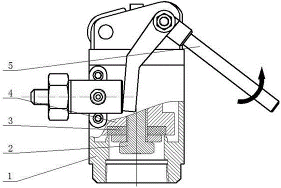
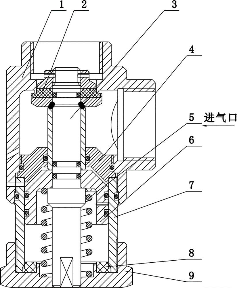
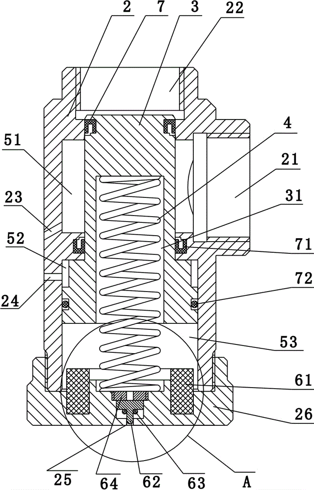
[0024] refer to Figure 3-6 As shown, an integrated selector valve includes a valve body 2, a piston 3 and a reset member 4. The outer diameter of the piston 3 is a variable diameter structure, the outer diameter of the piston 3 becomes larger from top to bottom, and the inner wall of the valve body 2 faces inward. Extend to form a boss structur...


PUM


Abstract

The invention discloses an integrated selection valve capable of being connected and matched with a drive device. The selection valve comprises a valve body, a piston capable of moving in the valve body and a reset piece. The valve body is provided with an air inlet and an air outlet. The piston is connected in the valve body in a sealing manner. A first space is formed between the upper portion of the piston and the inner wall of the valve body. The air inlet communicates with the first space. The valve body is provided with a first channel communicating with the first space and the drive device. A second space is formed between the lower portion of the piston and the inner wall of the valve body. The valve body is provided with a second channel communicating with the second space and the drive device. A third space is further formed between the bottom of the piston and the valve body and internally provided with a buffering structure capable of buffering the piston when the piston moves along the valve body. The integrated selection valve is small in opening force and good in sealing performance, action tests of 500 times can be achieved, the assembled structure is simple, and the service life is long.

Description

technical field [0001] The invention belongs to the field of gas fire extinguishing equipment, and in particular relates to an integrated selector valve. Background technique [0002] The traditional selector valve structure currently on the market is usually as follows: figure 1 As shown in the figure, 1 is a valve body, 2 is a compression bolt, 3 is a sealing gasket, 4 is a valve core, and 5 is a starting handle. When the selection valve is opened, the valve core will impact the pressing arm, and the pressing arm will impact the valve body, which will easily cause the deformation of the pressing arm. And it requires mechanical compression, such as figure 1 Among them, the sealing gasket needs the top screw to be compressed by rotating the threaded top valve core. When opening, the air pressure is pushed to the starting handle to start. The starting handle is rotated to open. When the push rod goes straight, it is subject to downward reverse force and is prone to deformat...

Claims


Application Information

Patent Timeline
Patent Type & Authority Applications(China)
IPC IPC(8): F16K31/06F16K1/00
CPCF16K31/0655F16K1/00
Inventor 朱登虎陈达伟钟允晖陈均汤本度
Owner 浙江信达可恩消防股份有限公司
Why Eureka
Try Eureka