Anti-fill and anti-dismantle valve for liquefied gas cylinder

A liquefied gas, anti-dismantle technology, applied in the direction of valve details, valve devices, valve operation/release devices, etc., can solve the safety hazards of liquefied gas cylinders, damage to the opening and closing of the valve core of the gas cylinder, and threaten the safety of users' lives and property and other issues to achieve the effect of protecting personal and property safety and improving safety performance

Active Publication Date: 2018-08-03
深圳安博智控科技有限公司
View PDF8 Cites 3 Cited by
  • Summary
  • Abstract
  • Description
  • Claims
  • Application Information

AI Technical Summary

Problems solved by technology

[0005] However, in the actual use of the above-mentioned valves, illegal operation or malicious damage caused the failure of the limited filling of the liquefied gas cylinder, resulting in a relatively large safety hazard in the use of the liquefied gas cylinder, which seriously threatened the safety of life and property of users.
[0006] To sum up, how to improve the problem of limited filling failure of liquefied gas cylinders caused by illegal operation or malicious damage, so as to reduce the potential safety hazards in the use of liquefied gas cylinders, is currently a technical problem to be solved urgently by those skilled in the art
[0007] In the existing technology, the valve core is easy to be opened, and the non-standard filling point is directly inflated with an air gun, causing damage to the opening and closing of the valve core of the gas cylinder, which directly affects the safety of the cylinder

Method used


Image

  • Anti-fill and anti-dismantle valve for liquefied gas cylinder
  • Anti-fill and anti-dismantle valve for liquefied gas cylinder
  • Anti-fill and anti-dismantle valve for liquefied gas cylinder

Examples


Embodiment 1

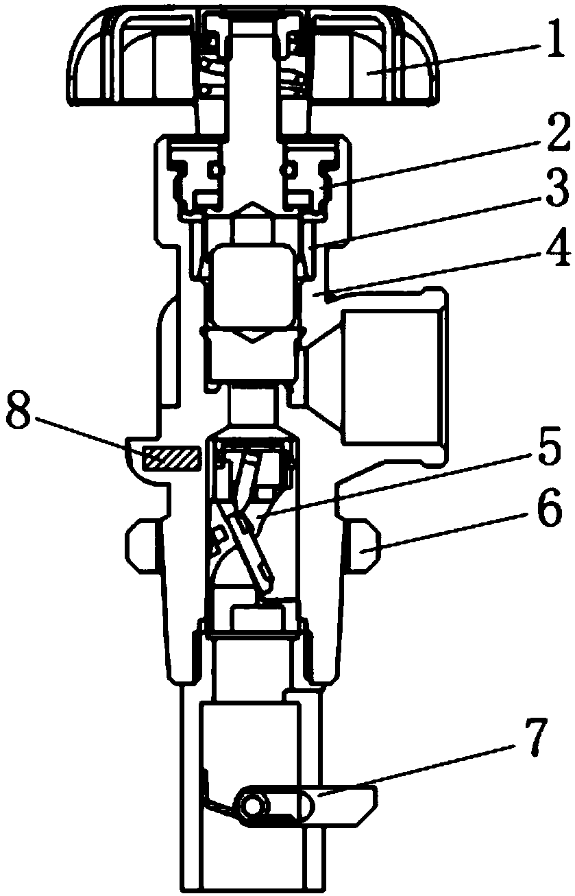
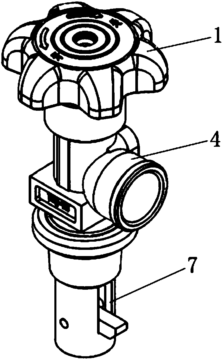
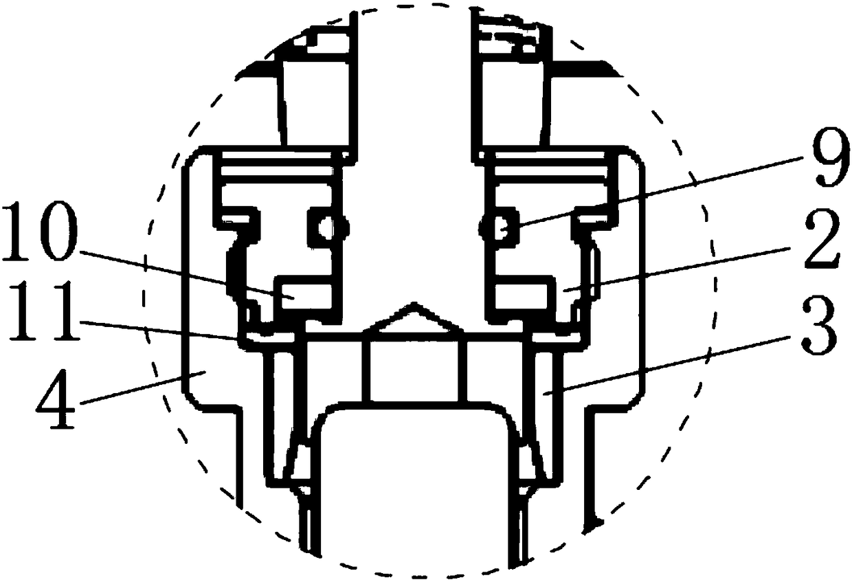
[0066] Embodiment 1: Valve top anti-disassembly device 2.

[0067] like Figure 3~10 As shown, the valve top anti-dismantlement device 2 is integrally formed and circular, with a through hole in the middle, and an external thread is provided on the outer wall of the valve top anti-dismantlement device 2, which is threadedly connected with the valve body 4 through the external thread. The external thread is an interference fit thread, the upper surface edge of the valve top anti-disassembly device 2 is in close contact with the inner wall of the valve body 4, and the upper end surface of the valve top anti-disassembly device 2 is provided with two anti-disassembly grooves 21, The two anti-disassembly grooves 21 are symmetrical with the above-mentioned through holes. An interference copper ring 3 is arranged below the valve top anti-disassembly device 2. The outer wall of the interference copper ring 3 is in close contact with the inner cavity wall of the valve body 4. The exces...

Embodiment 2

[0071] Embodiment 2: spool 5.

[0072] Please refer to the attached Figure 11~17 , the spool 5 is installed in the cavity of the valve body 4, the upper air inlet end of the spool 5 is connected to the diversion hole, and the lower air outlet end is connected to the air outlet in the valve body, the spool 5 includes a fairing 51, a spool Body 52, sealing plate 53, sealing plate clamping plate 54;

[0073] The spool body 52 is in the shape of a cylinder as a whole, and has an inclined groove on its side wall. The inclined groove separates the upper and lower flow channels of the valve core. An air guide hole 526 is provided, and a circle of collar is arranged on the edge of the air guide hole 526. The air guide hole 526 is connected to the disassembly hole 527 at the lower part of the valve core. The air guide hole 526 is the only air outlet hole of the inclined plane groove, and is used to export liquefied gas; The surface of the inclined-plane groove is also provided with ...

Embodiment 3

[0084] Embodiment 3: Anti-disassembly device 7 at the bottom of the valve.

[0085] Please refer to the attached Figure 18~21 The anti-dismantlement device 7 at the bottom of the valve is placed below the anti-dismantlement hole of the valve core, and the lower part of the valve body 4 is connected to the anti-dismantlement device. The anti-dismantlement device includes a filter plate 71 and an anti-dismantlement body 76. The upper part is a cylinder with a smaller outer diameter, and the lower part is a cylinder with a larger outer diameter. The two cylinders are connected together, and a filter sheet 71 is provided at the inlet port of the small cylinder; at the middle and lower area of ​​the inner cavity of the large cylinder, Two circular holes are arranged on the diameter of the anti-dismantlement main body 76 cavity walls, between the two circular holes, an anti-dismantlement assembly is arranged, the vertical direction of the side wall of the anti-dismantlement main b...


PUM


Abstract

The invention discloses an anti-charging anti-demounting valve for liquefied gas steel cylinders. The valve comprises a grip and a valve body, wherein the valve body is a three-way structure, the side opening is a charging port, the upper part is connected with the grip, and the lower part is connected with a valve bottom anti-demounting device; a valve top anti-demounting device is arranged in the vertical inner cavity of the valve body in the region above the charging part; an interference copper ring is arranged below the valve top anti-demounting device; and a valve core is arranged in the vertical inner cavity of the valve body in the region below the charging port. By arranging the double anti-demounting structures composed of the valve top anti-demounting device and the valve bottom anti-demounting device, the valve top anti-demounting device can only be demounted by a special demounting tool of a standard charging company, and the valve core in the middle region is provided with the anti-charging structure which can be charged only by a purpose-made air gun of the standard charging company, thereby ensuring the safety of the charged gas of the steel cylinder; and the valve bottom anti-demounting device is also an anti-demounting structure. By using the two anti-demounting structures and one anti-charging structure of the whole valve, the steel cylinder has favorable safety performance.

Description

technical field [0001] The invention relates to the technical field of liquefied gas filling, in particular to an anti-filling and anti-disassembly valve for a liquefied gas cylinder. Background technique [0002] In recent years, liquefied petroleum gas, as a new type of fuel, has rapidly entered thousands of households. However, due to the possible safety hazards of liquefied petroleum gas cylinders filled with liquefied petroleum gas, it will endanger the safety of users' personal and property safety. [0003] At present, in the liquefied gas filling industry, there are many informal filling points operating. These filling points have no filling qualifications, and the filling equipment and filling technology cannot meet the requirements stipulated by the state. There are great security risks. [0004] In order to ensure the safety of users' lives and property, the valves of the currently used liquefied gas cylinders have a fixed-point filling function, which makes the l...

Claims


Application Information

Patent Timeline
Patent Type & Authority Patents(China)
IPC IPC(8): F16K35/00F16K35/16F16K31/06
CPCF16K31/0644F16K35/00F16K35/16
Inventor 朱佳
Owner 深圳安博智控科技有限公司
Why Eureka
Try Eureka