Self-cleaning fluid metering device

A metering device and self-cleaning technology, applied in the field of metering, can solve the problems of increasing the contact wear of the remaining working surface, limiting the life of the metering device, etc., to achieve the effect of ensuring self-cleaning, avoiding metering errors, and preventing the accumulation of pollutants

Inactive Publication Date: 2016-11-09
唐翔
View PDF5 Cites 5 Cited by
  • Summary
  • Abstract
  • Description
  • Claims
  • Application Information

AI Technical Summary

Problems solved by technology

However, this solution has the major disadvantage of increasing the contact wear o

Method used


Image

  • Self-cleaning fluid metering device
  • Self-cleaning fluid metering device
  • Self-cleaning fluid metering device

Examples


Embodiment Construction

[0022] The principles and features of the present invention are described below in conjunction with the accompanying drawings, and the examples given are only used to explain the present invention, and are not intended to limit the scope of the present invention.

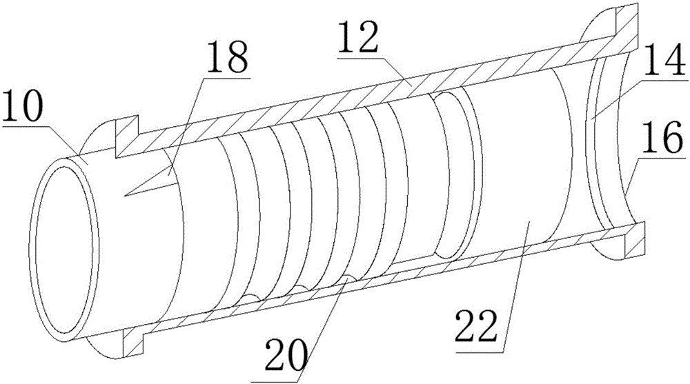
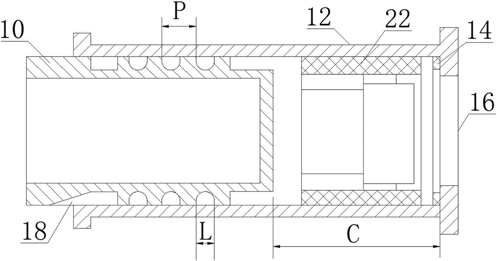
[0023] Such as figure 1 , figure 2 , image 3 As shown, a self-cleaning fluid metering device is used for metering fluid from a supply source to a device using the fluid, comprising a sleeve 12 and a metering valve 10 capable of sliding through a stroke C in the sleeve 12, the The sleeve 12 includes an inlet hole 16 for receiving fluid from the supply source, the metering valve 10 includes a hole for discharging the fluid to the device using the fluid, and the hole for discharging the fluid includes a drainage slot 18, which may be located outside said sleeve 12;

[0024] The self-cleaning fluid metering device also includes means 20 for directing fluid during movement of the metering valve 10 within the sleeve ...


PUM


Abstract

The invention relates to a self-cleaning fluid metering device. The self-cleaning fluid metering device is used for metering fluid from a supply source to a device using the fluid and comprises a sleeve and a metering valve which can slide a distance C in the sleeve, wherein the sleeve comprises an introduction hole used for receiving the fluid from the supply source, the metering valve comprises a hole used for discharging the fluid to the device using the fluid, and the hole used for discharging the fluid comprises one discharging slot which can be formed outside the sleeve. The self-cleaning fluid metering device has the beneficial effects that by virtue of structural design, the fluid is forced to wash out all the contact surfaces, so that self cleaning of the device is guaranteed, pollutants and the metered fluid are discharged out together, and accumulation of the pollutants and clamminess are prevented.

Description

technical field [0001] The invention relates to the metering field, in particular to a self-cleaning fluid metering device. Background technique [0002] In valves for calibration, it is known that the actuation of the guide path produces friction, which in turn produces hysteresis. This friction is always high due to the presence of contaminants in any fluid causing "stickiness" on the contact guide surfaces. [0003] In the specific case of fuel injection system metering devices, in turbojet or turboprop engines (more generally called turbines), this hysteresis leads to unevenness of the injection flow, which can impair the proper functioning of the turbine, especially in its when starting. [0004] Solutions to this problem have traditionally included reducing the frictional surface area. However, this solution has the major disadvantage of increasing the contact wear of the remaining working surfaces and thus limiting the lifetime of the metering device. Another solu...

Claims


Application Information

Patent Timeline
IPC IPC(8): G01F15/12
CPCG01F15/12
Inventor 唐翔
Owner 唐翔
Why Eureka
Try Eureka