Eureka AIR delivers breakthrough ideas for toughest innovation challenges, trusted by R&D personnel around the world.

Method for computing air impermeability of gas storage cavity

A calculation method and technology for gas storage chambers, which are applied in liquid/vacuum measurement for liquid tightness, fluid tightness testing, and testing of machine/structural components, etc., and can solve problems that have not been published yet.

Active Publication Date: 2016-11-09
SHANGHAI ELECTRIC POWER DESIGN INST
View PDF5 Cites 6 Cited by
  • Summary
  • Abstract
  • Description
  • Claims
  • Application Information

AI Technical Summary

Problems solved by technology

For the calculation of gas leakage in lined hard rock gas storage caverns, no one has published a relevant method

Method used


Image

  • Method for computing air impermeability of gas storage cavity
  • Method for computing air impermeability of gas storage cavity
  • Method for computing air impermeability of gas storage cavity

Examples


Embodiment

[0038] The airtightness of the gas storage chamber is one of the important parameters to evaluate the compressed air energy storage system, which directly affects the operating efficiency of the compressed air energy storage power station.

[0039] The purpose of the present invention is to provide a method for calculating the gas leakage of a gas storage chamber for compressed air energy storage, so as to provide the gas leakage under different lining permeability, and to ensure the gas storage by controlling the permeability of the lining. The airtightness of the chamber.

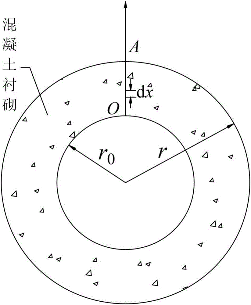
[0040] Such as figure 1 As shown, the gas storage cavern of the present invention is a spherical cavern, and the inner wall of the cavern is lined with a circle of concrete, and the concrete medium is uniform, that is, the pores in the concrete are also uniformly distributed, so it can be taken in a certain direction Analysis of air seepage.

[0041] Such as figure 1 As shown, assume that the radius of...


PUM


Abstract

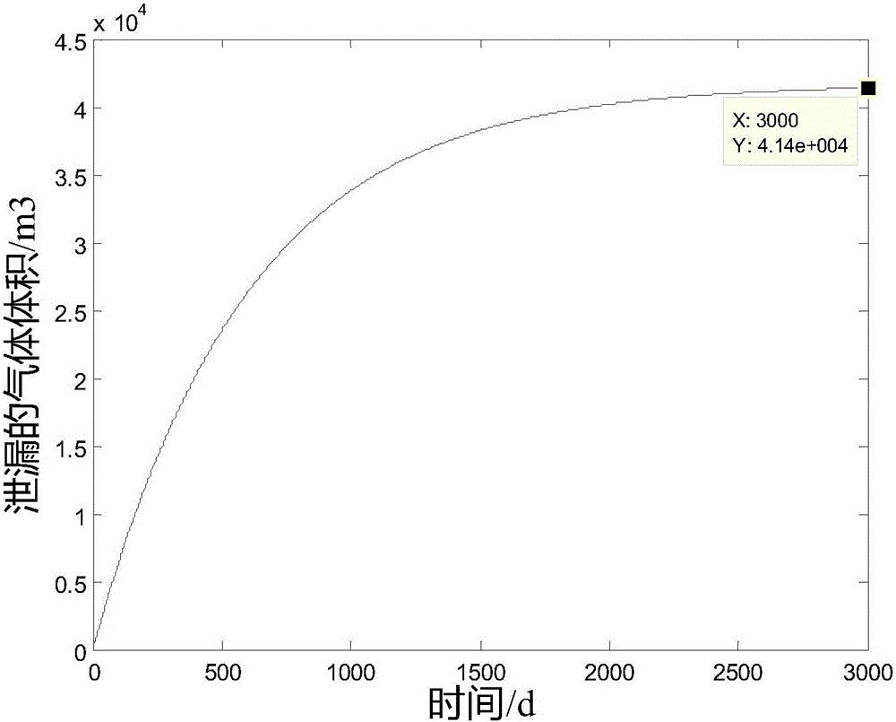
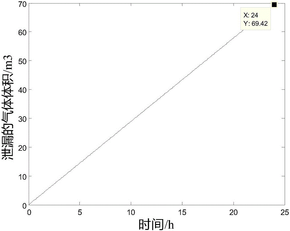
The invention discloses a method for computing the air impermeability of a gas storage cavity. The method comprises steps of: S1, setting seepage velocity computational formulas 1 for different seepage distances according to a Darcy law; S2, setting a computational formula 3 of the pressure difference [delta]px inside the cavity according to an ideal gas state equation computational formula 2; S3, supposing that the seepage velocity of a seeped gas is uA(t) when the gas reaches the outer surface of concrete, setting the leaked gas volume computational formula 4 within time dt; S4, setting the pore volume capable of containing air as V pore and obtaining a V pore computational formula 5; S5, setting the time when the gas just seep to a position A as a time start point and setting the volume of the seeped gas at the time t as [delta]V(t), setting a computational formula 6 of a pressure difference inside the cavity; and S6, integrating the computational formula 5 to obtain a differential equation, and solving the differential equation to obtain an expression of the volume of the leaked gas about time. The method may provide gas leakage cases with different lining permeability, and guarantees the air impermeability of the gas storage cavity by controlling the permeability of the lining.

Description

technical field [0001] The invention relates to a method for calculating the gas leakage status of a gas storage cavern. Background technique [0002] Compressed air energy storage system is another kind of electric energy storage system that can realize large-capacity and long-term electric energy storage. It stores excess electrical energy by compressing air, and releases high-pressure air through an expander to generate electricity when needed. The underground gas storage is an important part of the compressed air energy storage system, and it is the technical key to ensure its operating performance and reliability. [0003] Different from ordinary underground caverns, underground gas storage for compressed air energy storage needs to have good sealing to ensure that the sealed gas will not be lost and the working efficiency of the energy storage system can be guaranteed. [0004] As an emerging power storage technology, research on compressed gas energy storage is stil...

Claims


Application Information

Patent Timeline
Patent Type & Authority Applications(China)
IPC IPC(8): G01M3/32
CPCG01M3/3236
Inventor 彭益成叶斌程子睿叶为民陈永贵关雪飞
Owner SHANGHAI ELECTRIC POWER DESIGN INST
Why Eureka
Eureka Blog
Learn More