Device for power battery module side plate tensile test

A power battery and tensile test technology, applied in measuring devices, using stable tension/pressure to test the strength of materials, instruments, etc., can solve the problems of error in test results, loss of measurement meaning, and breaking of the module side panel shell. , to achieve the effect of improving the accuracy

Active Publication Date: 2016-11-09
BEIJING PRIDE NEW ENERGY BATTERY
View PDF5 Cites 4 Cited by
  • Summary
  • Abstract
  • Description
  • Claims
  • Application Information

AI Technical Summary

Problems solved by technology

Although this method has a simple structure, it cannot guarantee the accuracy of the position of the side plate of the module, nor can it guarantee the uniform force during the tensile test, and the clamp cannot clamp the side plate of the module when it is clamped. The center position of the side plate, so the error of the test result is very large, and sometimes even loses the meaning of measurement; on the other hand, because the pressure plate often only presses a part of the side plate of the module, the test result will also be inaccurate. It will also cause the possibility of breaking the module side panel shell directly

Method used


Image

  • Device for power battery module side plate tensile test
  • Device for power battery module side plate tensile test
  • Device for power battery module side plate tensile test

Examples


Embodiment Construction

[0033] The principles and features of the present invention are described below in conjunction with the accompanying drawings, and the examples given are only used to explain the present invention, and are not intended to limit the scope of the present invention.

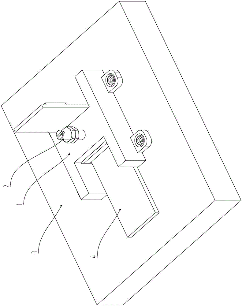
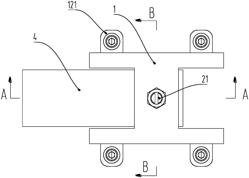
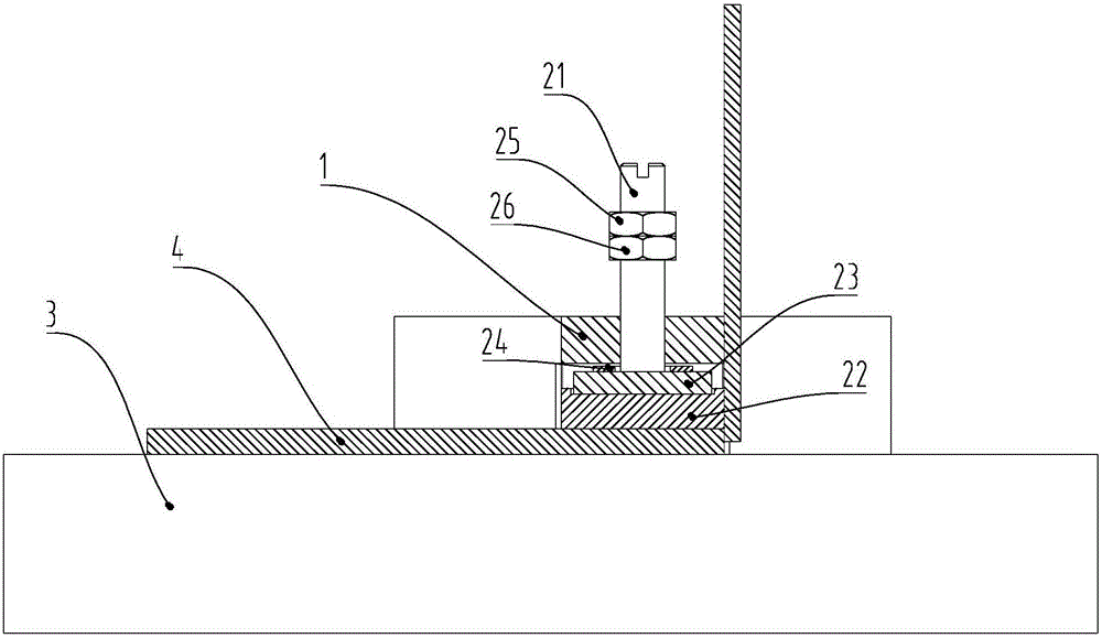
[0034] Such as figure 1 and Figure 6 shown, figure 1 It is a schematic diagram of the installation of the device used for the tensile test of the side plate of the power battery module provided by the present invention during operation; figure 2 It is a top view of a device used for tensile test of power battery module side plate provided by the present invention; image 3 for along figure 2 Schematic diagram of the cross-section in the A-A direction; Figure 4 for along figure 2 Schematic cross-sectional view of B-B direction; Figure 5 It is a schematic diagram of a partially cut three-dimensional structure of a device for tensile test of a power battery module side plate provided by the present inventio...


PUM


Abstract

The invention provides a device for a power battery module side plate tensile test. The device comprises a base and a compression assembly. The base is fixed to a test table and provided with a threaded hole. The compression assembly comprises a vertically-arranged screw rod and a pressing plate horizontally installed at the lower end of the screw rod. The upper end of the screw rod penetrates out of the threaded hole, and the screw rod is in threaded connection with the threaded hole. The pressing plate is located between the base and the test table. The pressing plate can rotate along with the screw rod in the threaded hole so as to move up and down. The device is fixed to the test table and can accurately fix and press a power battery module, and accuracy of the tensile test can be greatly improved.

Description

technical field [0001] The invention relates to the field of electric vehicles, in particular to a device for tensile testing the side plate of a power battery module. Background technique [0002] my country is currently in the period of vehicle energy conversion, and new energy vehicles are increasing day by day. In major enterprises, the safety of new energy vehicles has attracted more and more attention. As the power source of new energy vehicles, the power battery module is self-evident, so it is necessary to carry out safety inspections on all parts of the power battery module to ensure that it meets the safety standards when it leaves the factory. In the various tests of the power battery module, it is necessary to conduct a tensile test on the welding performance of the side plate of the module. Usually, it is necessary to cut off the side plate of the module, and only keep one side plate. The L-shaped weldment formed by welding the plate and an end plate is used as...

Claims


Application Information

Patent Timeline
Patent Type & Authority Applications(China)
IPC IPC(8): G01N3/04G01N3/08
CPCG01N3/04G01N3/08
Inventor 李鸿键王小龙盛力赵孟
Owner BEIJING PRIDE NEW ENERGY BATTERY
Why Eureka
Try Eureka