
A thermal imager lens protection device for protecting composite material chips

A protection device and composite material technology, applied in instruments, optical filters for photography, cameras, etc., can solve problems such as inability to protect, and achieve the effect of universality and chip protection

Active Publication Date: 2019-03-05
DALIAN UNIV OF TECH
View PDF7 Cites 0 Cited by
  • Summary
  • Abstract
  • Description
  • Claims
  • Application Information

AI Technical Summary

Problems solved by technology

The device can only protect the lens when the lens is not working, but cannot protect the lens when it is working in a relatively harsh environment

Method used


Image

  • A thermal imager lens protection device for protecting composite material chips

Examples


Embodiment Construction

[0010] The present invention will be further described below in conjunction with the accompanying drawings and specific embodiments.

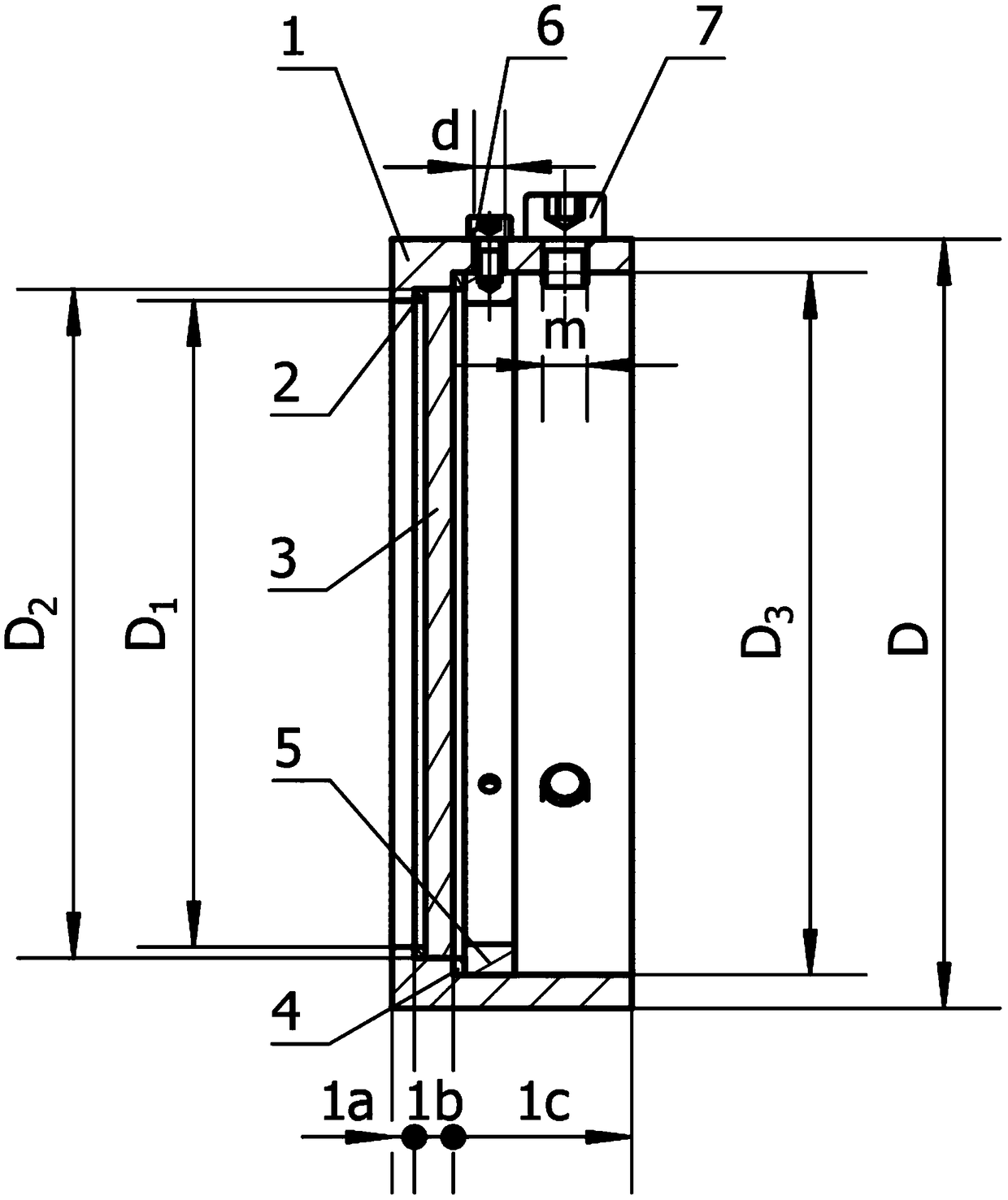
[0011] figure 1 It is a cross-sectional view of the assembly of the thermal imager lens protection device of the present invention. When in use, the thermal imager lens protection device is installed on the front end of the thermal imager lens to protect the lens and realize safe work when cutting composite materials. The size of the thermal imager lens protection device can be adjusted accordingly according to the lens size of the thermal imager, and the invention has universal applicability.

[0012] The device includes a housing 1, small and large nylon gaskets 2, 4, calcium fluoride wafer 3 and positioning gasket 5, screws 6, and connecting screws 7; the small nylon gasket 2 is installed on the second stepped ring 1b of the housing 1 At the edge of the first stepped ring 1a, the calcium fluoride wafer 3 is placed in the second stepped ring...


PUM


Abstract

The invention relates to a thermal imager lens protection device for protecting composite material chips, belonging to the technical field of lens protection, and in particular to a thermal imager lens protection device for protecting composite material chips. The device includes a shell, small and large nylon gaskets, calcium fluoride wafers, positioning gaskets, screws and connecting screws. The small nylon gasket is installed at the edge of the second stepped ring and the first stepped ring of the casing, and the calcium fluoride wafer is placed in the second stepped ring of the casing, close to the small nylon gasket. The large nylon spacer is installed on the edge of the third stepped ring and the second stepped ring of the housing, and the positioning spacer is installed in the third stepped ring of the housing to be close to the large nylon spacer. The positioning gasket is fixed in the housing by three screws, and then the thermal imager lens protection device is connected to the lens by three connecting screws. The device uses calcium fluoride wafers to effectively protect chips when cutting composite materials, protect the lens of the thermal imager, and realize safe work when cutting composite materials.

Description

technical field [0001] The invention belongs to the technical field of lens protection, and in particular relates to a thermal imager lens protection device for protecting composite material chips. Background technique [0002] Thermal imaging cameras are widely used in military, medical and other fields due to their good smoke and dust penetration capabilities, high sensitivity and high resolution. However, the cutting of composite materials is different from the curly strip-shaped chips produced by general cutting of metal materials, but the chips are broken. At this time, the working environment of the thermal imager is relatively harsh, and the lens is easily damaged. At present, UV mirrors are widely used for lens protection of cameras, but because the UV mirrors are circular, have limited size and are connected with the camera by threads, when the lens is non-circular, the size does not meet the requirements of UV mirrors, or there is no connecting thread , UV mirror ...

Claims


Application Information

Patent Timeline
Patent Type & Authority Patents(China)
IPC IPC(8): G03B11/04
CPCG03B11/045
Inventor 贾振元白玉付饶王福吉郭会彬钱宝伟
Owner DALIAN UNIV OF TECH
Learn More