
3D visual machine room monitoring system

A monitoring system and computer room technology, applied in general control systems, control/regulation systems, computer control, etc., can solve problems such as reduced efficiency, lack of sense of position and globality, and no intuitive display, so as to reduce operation and maintenance costs and improve Monitoring efficiency, intuitive and clear display effect

Inactive Publication Date: 2016-11-09
INSPUR BEIJING ELECTRONICS INFORMATION IND
View PDF3 Cites 16 Cited by
  • Summary
  • Abstract
  • Description
  • Claims
  • Application Information

AI Technical Summary

Problems solved by technology

[0003] However, in the traditional computer room monitoring system, the monitoring data and parameters of each device in the computer room are separated from each other, and the monitoring data and parameters of the equipment are not managed uniformly, which makes it difficult to call the monitoring data and parameters of the equipment, and the operation efficiency of the data center is low. The cost of maintenance is high; at the same time, the monitoring interface of the traditional monitoring system is mostly displayed in the form of simple text and forms. The shape of each device itself, the corresponding device monitoring data and device parameters are not intuitively displayed, lacking a sense of location and overall situation. Make it impossible for monitoring personnel to quickly locate the equipment, making analysis difficult and reducing efficiency

Method used


Image

  • 3D visual machine room monitoring system

Examples


Embodiment Construction

[0030] The following will clearly and completely describe the technical solutions in the embodiments of the present invention with reference to the accompanying drawings in the embodiments of the present invention. Obviously, the described embodiments are only some, not all, embodiments of the present invention. Based on the embodiments of the present invention, all other embodiments obtained by persons of ordinary skill in the art without making creative efforts belong to the protection scope of the present invention.

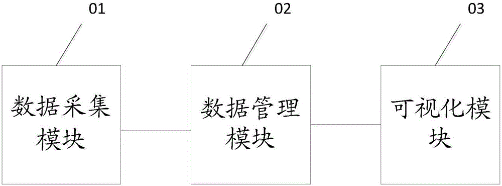
[0031] see figure 1 , figure 1 It is a schematic diagram of a 3D visualization computer room monitoring system provided by an embodiment of the present invention.

[0032] In a specific embodiment, a 3D visualization computer room monitoring system is provided, including: a data collection module 01 for acquiring environmental monitoring data inside the computer room and equipment monitoring data corresponding to each power distribution equipment; The acquis...


PUM


Abstract

The application discloses a 3D visual machine room monitoring system comprising a data acquisition module, a data management module, and a visual module. The data acquisition module is used for obtaining environment monitoring data inside a machine room as well as equipment monitoring data corresponding to all distribution equipment; the data management module connected with the data acquisition module is used for realizing one-to-one correspondence between the equipment monitoring data and pre-inputted equipment parameters to form distribution equipment information and carrying out integration of the distribution equipment information and the equipment monitoring data; and the visual module connected with the data management module is used for carrying out 3D displaying of the distribution equipment and displaying the distribution equipment information and / or environment monitoring data in a reform mode. With the data management module, the monitoring convenience is improved; the monitoring efficiency and the system operation efficiency are enhanced; and the operation and maintenance costs are lowered. The 3D displaying of the distribution equipment is realized by the visual module and the distribution equipment information and / or environment monitoring data are / is displayed in a report mode, so that the distribution equipment, the environment monitoring data, and the distribution equipment information can be displayed visual and clearly.

Description

technical field [0001] The invention relates to the technical field of machine room monitoring, and more specifically, relates to a 3D visualized machine room monitoring system. Background technique [0002] The computer room is an important place for information processing and exchange. It is very important to monitor the computer room environment in real time and effectively to ensure the safe operation of the computer room. At the same time, the convenient and fast monitoring of the computer room environment not only enables the monitoring personnel to quickly call the equipment data in the computer room, but also facilitates timely problem solving. . [0003] However, in the traditional computer room monitoring system, the monitoring data and parameters of each device in the computer room are separated from each other, and the monitoring data and parameters of the equipment are not managed uniformly, which makes it difficult to call the monitoring data and parameters of ...

Claims


Application Information

Patent Timeline
IPC IPC(8): G05B19/048
CPCG05B19/048
Inventor 荆君高飞张俊雷
Owner INSPUR BEIJING ELECTRONICS INFORMATION IND
Learn More