
Method and device for determining characteristic curve of pipe network

A characteristic curve and pipe network technology, applied in special data processing applications, complex mathematical operations, other database retrievals, etc., can solve the problems of increasing the output of the pump, inapplicability of the proportional law, and unfavorable requirements for energy saving, and achieve the goal of improving efficiency. Effect

Active Publication Date: 2016-11-09
ENN ENERGY SERVICE
View PDF7 Cites 2 Cited by
  • Summary
  • Abstract
  • Description
  • Claims
  • Application Information

AI Technical Summary

Problems solved by technology

However, in the HVAC system, real-time load changes will often require the adjustment of resistance devices in the pipeline, and the result of the adjustment will change the characteristic curve of the entire pipeline network
Because the law of this change is very complicated, it is impossible to calculate the characteristic curve of the pipe network in detail, so the hydraulic operating point cannot be calculated, which makes it possible to maintain the pressure difference or increase the lift as much as possible during hydraulic adjustment, resulting in energy consumption of the transportation system Remaining high, very unfavorable to the requirements for energy saving
[0003] At present, in order to calculate the hydraulic operating point, usually the characteristic curve of the pipe network is kept unchanged, and a simple proportional law is used for calculation; or it is easier to increase the output of the water pump by adjusting the pressure difference, which will cause a vicious circle
Moreover, for existing open systems and systems with back pressure, the proportional law is completely inapplicable and cannot be simply applied

Method used


Image

  • Method and device for determining characteristic curve of pipe network
  • Method and device for determining characteristic curve of pipe network
  • Method and device for determining characteristic curve of pipe network

Examples


Embodiment Construction

[0037] In order to make the purpose, technical solutions and advantages of the present invention clearer, the present invention will be further described in detail below in conjunction with the accompanying drawings. Obviously, the described embodiments are only some of the embodiments of the present invention, rather than all of them. Based on the embodiments of the present invention, all other embodiments obtained by persons of ordinary skill in the art without making creative efforts belong to the protection scope of the present invention.

[0038] The embodiment of the present invention provides a new idea of ​​determining the characteristic curve of the pipe network from the perspective of the combination type of the circulation equipment, wherein the combination type of the circulation equipment may specifically refer to the combination type in which the water inlet valve of the energy supply main equipment is opened. Specifically, the inventor obtained various influencin...


PUM


Abstract

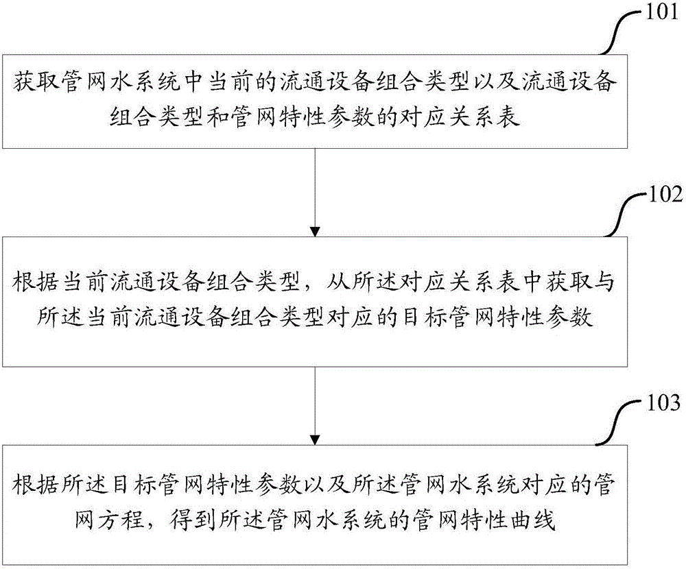
The invention discloses a method and device for determining a characteristic curve of a pipe network. A present combination type of circulation equipment in a pipe network water system and a correspondence table between the combination types of the circulation equipment and characteristic parameters of the pipeline are obtained; according to the present combination type of the circulation equipment, a target pipe network characteristic parameter corresponding to the present combination type of the circulation equipment is obtained from the correspondence table; and according to the target pipe network characteristic parameter and a pipe network equation corresponding to the pipe network water system, the pipe network characteristic curve of the pipe network water system is obtained. Thus, a new ideal for determining the pipe network characteristic curve is provided from the aspect of the combination type of the circulation equipment, the target pipe network characteristic parameter corresponding to the present combination type of the circulation equipment can be obtained rapidly and accurately according to the correspondence table, and thus, the pipe network characteristic curve can be determined more efficiently and more accurately.

Description

technical field [0001] The invention relates to the technical field of water pump working condition operation control, in particular to a method and device for determining a characteristic curve of a pipe network. Background technique [0002] Theoretically speaking, the hydraulic working point can be obtained by calculating the point where the working point of the water pump intersects the characteristic curve of the pipe network. However, in the HVAC system, the real-time change of the load will often require the adjustment of the resistance device in the pipeline, and the result of the adjustment will cause the characteristic curve of the entire pipeline network to change. Because the law of this change is very complicated, it is impossible to calculate the characteristic curve of the pipe network in detail, so the hydraulic operating point cannot be calculated, which makes it possible to maintain the pressure difference or increase the lift as much as possible during hyd...

Claims


Application Information

Patent Timeline
IPC IPC(8): G06Q50/06G06F17/11G06F17/30
CPCG06F16/903G06F17/11G06Q50/06
Inventor 宋志春乔林基王亚静纪朝阳
Owner ENN ENERGY SERVICE
Learn More