This helps you quickly interpret patents by identifying the three key elements:
Problems solved by technology
Method used
Benefits of technology
Problems solved by technology
The smaller the Swing value, the better the EMI result, but it may cause the chip-on-chip S-COF to fail to read the data correctly
Method used
Image
Click on the blue label to locate the original text in one second.
Reading with bidirectional positioning of images and text.
Examples
Embodiment 1
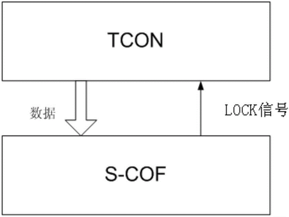
[0037] Embodiment 1: This embodiment provides a driving method for reducing electromagnetic interference when transmitting differential signals, including:
[0038] When No. 2 chip verifies that the data transmitted from No. 1 chip is correct and the Swing value of the transmitted data is the smallest, No. 1 chip and No. 2 chip keep the original data transmission parameters to work.
[0039] In a preferred embodiment, the Swing initial value of the transmitted data is set to the minimum value, and when the No. 2 chip verifies that the data transmitted by the No. 1 chip is incorrect, the Swing value of the transmitted data at this time is increased by one level until the No. 2 chip Verify that the data transmitted by chip No. 1 is correct.
[0040] The No. 2 chip verifies that the data transmitted from the No. 1 chip is correct, specifically:
[0041] The data received by the No. 2 chip is the same as the initial data A of the built-in storage. The No. 1 chip transmits the sam...
Embodiment 2
[0052] combine figure 2 Describe this implementation mode, a driving device for reducing electromagnetic interference, the driving device includes No. 1 chip and No. 2 chip;
[0053] Chip No. 1 is used to transmit data to Chip No. 2. When it is determined that the data read by Chip No. 2 is correct, keep the original data transmission parameters working. When it is determined that the data read by Chip No. 2 is incorrect, increase the Swing value of the transmitted data. level one;
[0054] No. 2 chip judges whether the read transmission data is correct, and returns the judgment result to No. 1 chip. If it is correct, the original data transmission parameters are kept working.
[0055] In a preferred embodiment, the initial value of the Swing of the transmitted data is set to a minimum value.
[0056] In a preferred embodiment, said judging whether the read transmission data is correct specifically includes:
[0057] Whether the data received by the No. 2 chip is the same ...
PUM
Abstract
The application provides a driving method and a driving device for reducing electromagnetic interference. The driving method for driving a Source-Chip on Film (S-COF) and a Timing Controller (TCON) comprises the steps that: firstly the TCON outputs initial data A stored by the S-COF; whether received data is right or not is judged by comparing transmission data received by the S-COF with built-in initial data A, if not, the TCON performs corresponding adjustments on a Swing value of the transmission data mini-LVDS; and finally the Swing value is a minimum value which ensures that the S-COF can smoothly read the data, and at this time, the S-COF and the TCON keep the initial data transmission parameter works.
Description
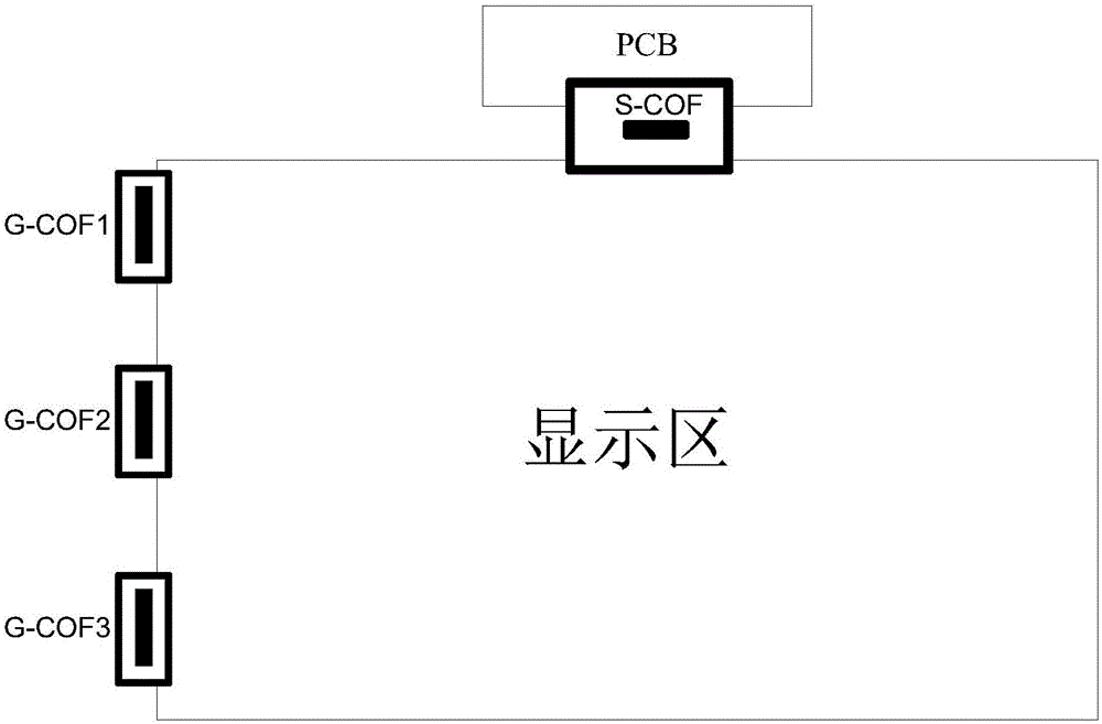
technical field [0001] The invention relates to the technical field of liquid crystal display, in particular to a driving method and a driving device for reducing electromagnetic interference in a TFT-LCD. Background technique [0002] TFT-LCD (Thin Film TransistorLiquid Crystal Display, Thin Film TransistorLiquid Crystal Display) is one of the main varieties of flat panel display, and has become an important display platform in modern IT and video products. The main driving principle of TFT-LCD is that the main board of the system connects the R / G / B compression signal, control signal and power to the connector on the PCB board through the wire, and the data passes through the timing controller TCON (Timing Controller, timing controller) on the PCB board. ) After the IC is processed, it is connected to the display area through the PCB board through the data chip-on-film S-COF (Source-Chip on Film, data chip-on-film) and G-COF (Gate-Chip on Film, gate chip-on-film) , so th...
Claims
Application Information
Patent Timeline
Application Date:The date an application was filed.
Publication Date:The date a patent or application was officially published.
First Publication Date:The earliest publication date of a patent with the same application number.
Issue Date:Publication date of the patent grant document.
PCT Entry Date:The Entry date of PCT National Phase.
Estimated Expiry Date:The statutory expiry date of a patent right according to the Patent Law, and it is the longest term of protection that the patent right can achieve without the termination of the patent right due to other reasons(Term extension factor has been taken into account ).
Invalid Date:Actual expiry date is based on effective date or publication date of legal transaction data of invalid patent.

