Built-in tangential-type rotor core, built-in tangential-type rotor, and motor
A rotor core and iron core technology, applied in the field of built-in tangential rotors, can solve problems such as motor rotor demagnetization, achieve the effects of improving reliability, solving rotor demagnetization, and improving utilization
- Summary
- Abstract
- Description
- Claims
- Application Information
AI Technical Summary
Problems solved by technology
Method used
Image

Examples
Embodiment 1
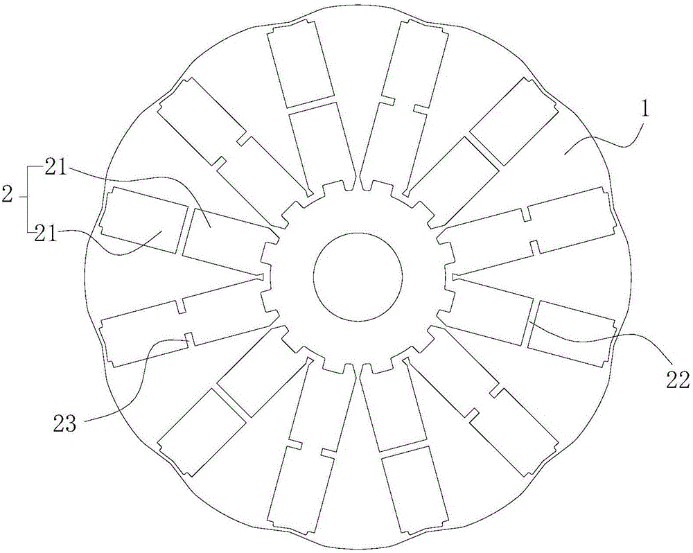
[0031] The preferred embodiment discloses a built-in tangential rotor core. Such as figure 2 and image 3 As shown, the rotor core includes a core body 1 and a plurality of magnetic tile grooves 2 extending radially along the core body 1, at least two magnetic tiles are formed in at least one of the magnetic tile grooves 2 As for the fixing structure 21, two adjacent magnetic tile fixing structures 21 in each magnetic tile groove 2 are at least partially isolated from each other.
[0032] The interior of the magnetic tile groove is at least partially isolated from each other. Different magnetic tile fixing structures can use rotor magnetic tiles with different performances to improve the utilization rate of the rotor magnetic tiles; it can effectively solve the problem of motor rotor demagnetization during the operation of the motor and improve the reliability of the motor. sex.
[0033] Specifically, the magnetic tile groove 2 formed with at least two magnetic tile fixing...
Embodiment 2
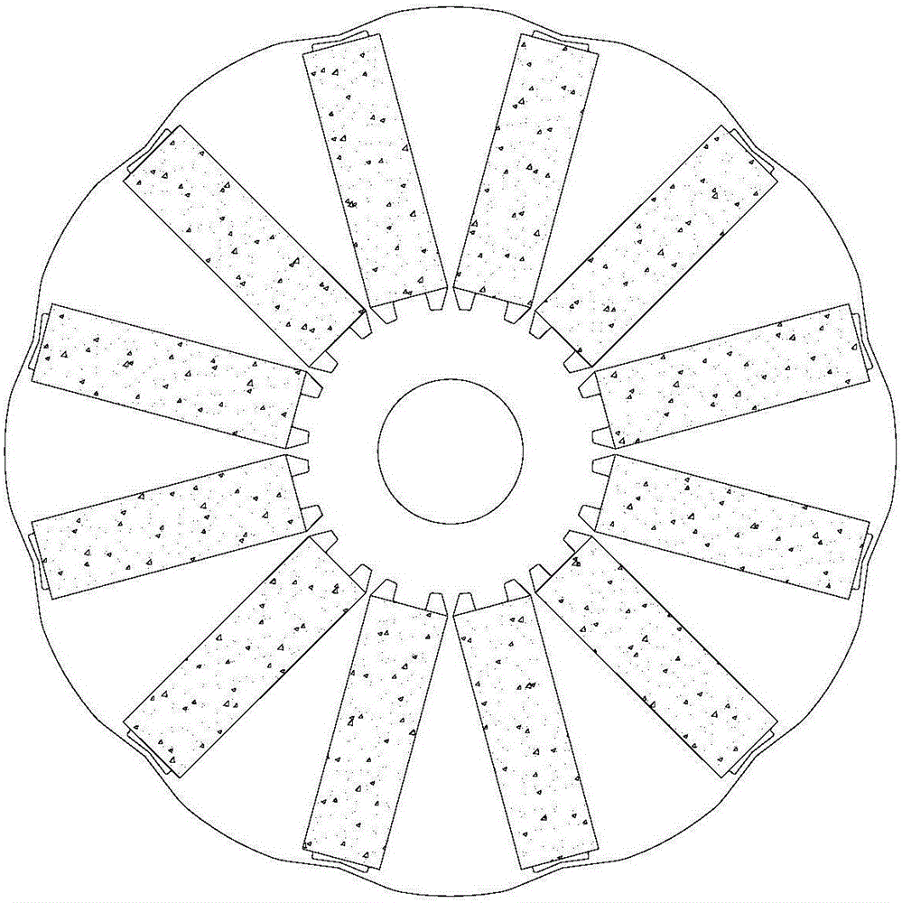
[0038] This preferred embodiment discloses a built-in tangential rotor. Such as Figure 4 As mentioned above, the rotor includes magnetic tiles 3 and various rotor cores as described in the first preferred embodiment. At least two independent magnetic tiles 3 are installed in at least one magnetic tile slot 2 of the rotor core, and each magnetic tile 3 is pressed into and fixed in a magnetic tile fixing structure 21 with glue.
[0039] The two magnetic tiles in the magnetic tile groove are independent of each other. This segmented structure can give full play to the performance of the magnetic tiles at different positions, facilitate the replacement of the magnetic tiles separately, and reduce the risk of motor demagnetization.
[0040] The two magnetic tiles 3 in each magnetic tile groove 2 are independent of each other, so different magnetic tiles 3 can be arranged respectively according to needs. That is, the magnetic tiles 3 in the rotor can form various matching schemes...
Embodiment 3
[0043] This preferred embodiment discloses a built-in tangential rotor, the structure of which is basically the same as that of preferred embodiment 2, the difference is that, as Figure 5 As mentioned above, in the magnetic tile groove 2 installed with at least two mutually independent magnetic tiles 3, the at least two magnetic tiles 3 are magnetic tiles of different types.
[0044] In view of the fact that the magnetic tile 3 is easily demagnetized due to the air gap magnetic field near the edge of the air gap (the air gap here refers to the gap formed between the outer wall of the rotor and the inner wall of the stator), so preferably, it is arranged near the edge of the air gap. Compared with the magnetic tiles 3 arranged far away from the edge of the air gap, the magnetic tiles 3 at Tile 3 has higher magnetic properties, preventing demagnetization while saving costs.
PUM
 Abstract
Description
Claims
Application Information
 - R&D
- Intellectual Property
- Life Sciences
- Materials
- Tech Scout
- Unparalleled Data Quality
- Higher Quality Content
- 60% Fewer Hallucinations
Browse by: Latest US Patents, China's latest patents, Technical Efficacy Thesaurus, Application Domain, Technology Topic, Popular Technical Reports.
© 2025 PatSnap. All rights reserved.Legal|Privacy policy|Modern Slavery Act Transparency Statement|Sitemap|About US| Contact US: help@patsnap.com