Rotor for rotary electric machine

Inactive Publication Date: 2006-03-16
NISSAN MOTOR CO LTD +1
View PDF6 Cites 10 Cited by
  • Summary
  • Abstract
  • Description
  • Claims
  • Application Information

AI Technical Summary

Benefits of technology

[0004] It is an object of the present invention to provide a rotor for a rotary electric machin

Problems solved by technology

This NeFeBr permanent magnets are demagnetized in a high temperature state or in a state to be applied with high reverse magnetic field, and thereby can n

Method used


Image

  • Rotor for rotary electric machine
  • Rotor for rotary electric machine
  • Rotor for rotary electric machine

Examples


first embodiment

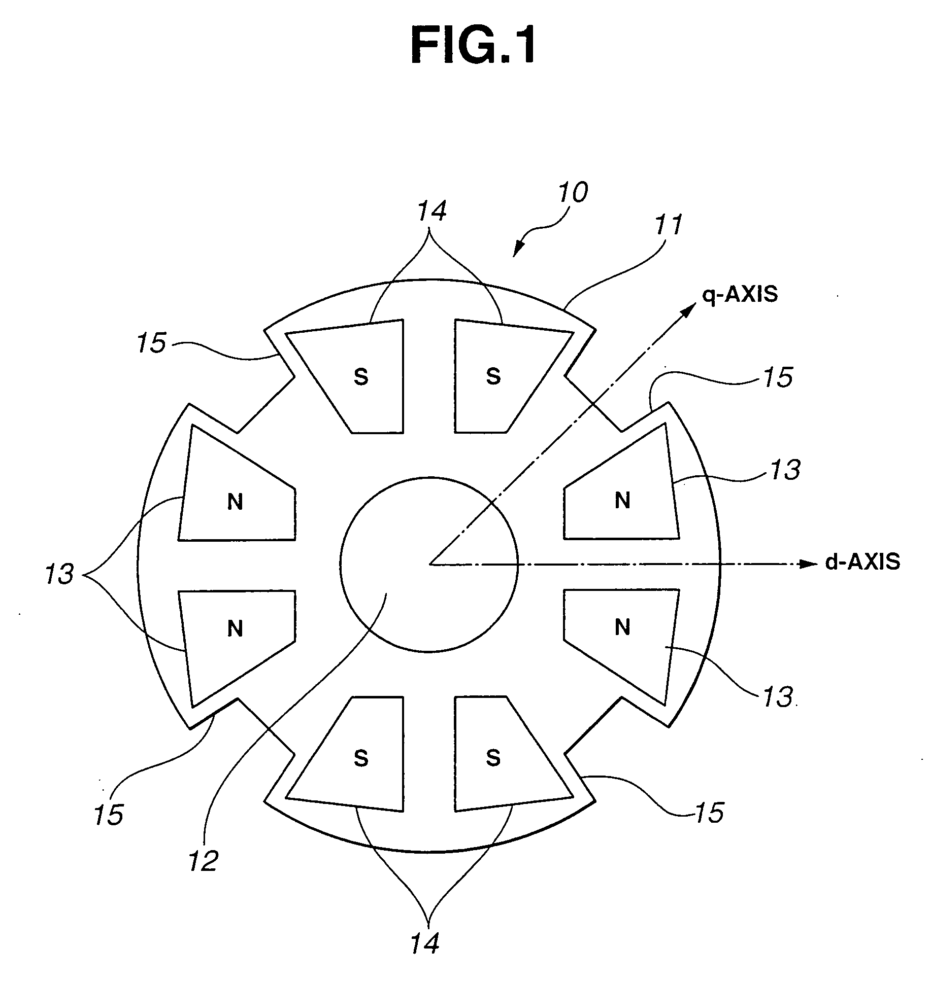
[0011]FIG. 1 shows a rotor 10 for a rotary electric machine according to the present invention. As shown in FIG. 1, rotor 10 of the rotary electric machine includes a rotor core 11 being in the form of a disk, a shaft 12 being a rotating shaft of rotor core 11, a plurality of N pole permanent magnets 13, and a plurality of S pole permanent magnets 14. Rotor core 11 is made of magnetic material such as laminated magnetic steel sheets. Rotor core 11 includes a plurality of magnet sets each including a pair of N pole permanent magnets 13 or a pair of S pole permanent magnets 14. Near the outer circumference of rotor core 11, there are provided a plurality of the pairs (or the magnet sets) of N pole permanent magnets 13 and a plurality of the pairs (or the magnet sets) of S pole permanent magnets 14. The pairs of N pole permanent magnets 13 and the pairs of S pole permanent magnets 14 are alternately arranged in a circumferential direction of rotor core 11. (in FIG. 1, there are two pai...

second embodiment

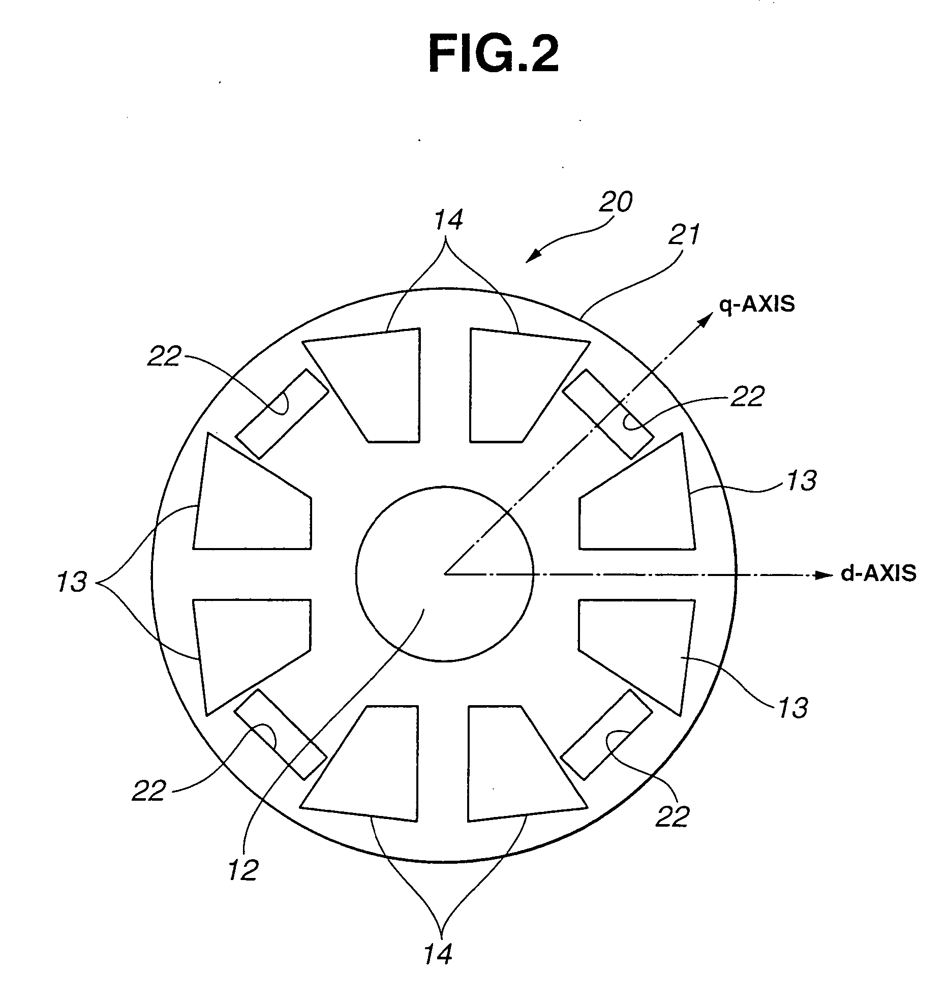
[0018]FIG. 2 shows a rotor 20 for a rotary electric machine according to the present invention. As shown in FIG. 2, rotor 20 of the rotary electric machine includes a rotor core 21, slits 22 employed in place of recessed portions 15, and each having opening being in the form of a wider rectangular shape. Each slit 22 is so formed that longer sides thereof are perpendicular to the q-axis. Each slit 22 is located at a radial position slightly outside a center position of the radial length of one of permanent magnets 13 and 14. Between adjacent two of the permanent magnets of the opposite polarities, there is provided one slit 22 as the air layer. In the other respects, rotor 20 is substantially identical to rotor 10 in structure and operation. Accordingly, the q-axis reluctance is higher than the d-axis reluctance, and it is possible to achieve the saliency.

third embodiment

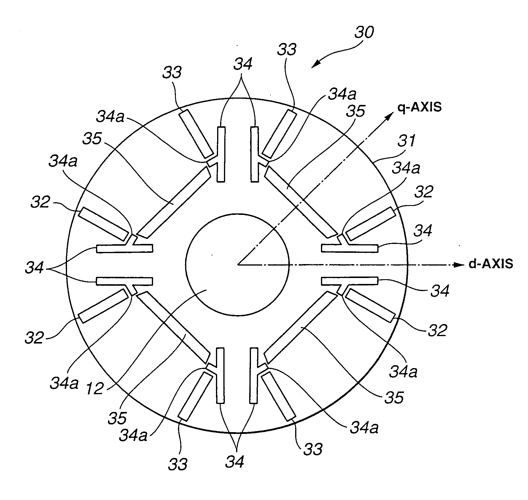
[0019]FIG. 3 shows a rotor 30 for a rotary electric machine according to the present invention. As shown in FIG. 3, rotor 30 of the rotary electric machine includes a rotor core 31 provided with N pole permanent magnets 32 and S pole permanent magnets 33. Each of N pole permanent magnets 32 and S pole permanent magnets 33 is in the form of a narrow rectangular shape or elongated rectangular shape in the plane, and has longer sides extending substantially along the radial direction of the rotor core. Adjacent two of N pole permanent magnets 32 are paired in a V-shaped form, and arranged circumferentially at a predetermined angle. Adjacent two of S pole permanent magnets 33 are paired in a V-shaped form, and arranged circumferentially at a predetermined angle. That is, two permanent magnets of each magnet set are arranged to be tapered to the center of rotor core 31. Between adjacent two of the permanent magnets of the same polarity, there are provided two first slits 34, 34. Between ...


PUM


Abstract

A rotor for a rotary electric machine includes a rotor core made of magnetic material, and being in the form of a disk, and a plurality of magnet sets each including a pair of permanent magnets whose polarities are identical to each other. The magnet sets are arranged circumferentially in the rotor core so that the polarities of the magnet sets change alternately. The rotor core includes nonmagnetic portions each formed between adjacent two of the magnet sets.

Description

BACKGROUND OF THE INVENTION [0001] The present invention relates to a rotor for a rotary electric machine, and more especially to a rotor for a rotary electric machine such as a permanent magnet motor. [0002] Japanese patent application publication No. 2004-96868 shows a rotary electric machine being an IPM (Interior Permanent Magnet) motor including a rotor, and a plurality of permanent magnets embedded in the rotor. This motor has magnetic reluctance in a direction between N pole of each permanent magnet and S pole of one permanent magnet being lower than magnetic reluctance in a direction of N pole of one permanent magnet. The motor generates reluctance torque by a difference in magnetic reluctance between d-axis and q-axis. SUMMARY OF THE INVENTION [0003] However, the conventional IPM motor uses NeFeBr permanent magnets with high BHmax. This NeFeBr permanent magnets are demagnetized in a high temperature state or in a state to be applied with high reverse magnetic field, and the...

Claims


Application Information

Patent Timeline
IPC IPC(8): H02K21/12H02K1/27
CPCH02K1/2766
Inventor ARIMITSU, MINORUAKATSU, KAN
Owner NISSAN MOTOR CO LTD
Why Eureka
Try Eureka