Supercharge Your Innovation With Domain-Expert AI Agents!

Self-adaptive dynamic balance structure of motor and adjusting method thereof

An adaptive, motor shaft technology, applied in the direction of electric components, magnetic circuit shape/style/structure, electrical components, etc., can solve the problems of increasing the weight of the motor body, falling off, etc., and achieve the effect of reducing the number of adjustments and covering a large area

Inactive Publication Date: 2016-11-09
TIANJIN SANTROLL ELECTRIC AUTOMOBILE TECH CO LTD
View PDF0 Cites 0 Cited by
  • Summary
  • Abstract
  • Description
  • Claims
  • Application Information

AI Technical Summary

Problems solved by technology

[0003] The existing method to reduce the initial dynamic unbalance is: set a number of round holes near the outer ring of the end plate, add lead or copper blocks to adjust the unbalance by adding weight, and solidify it with balance cement. The position of the round hole cannot be spread all over the end plate, so for many phase imbalances, the only way to achieve dynamic balance is to add balance cement to multiple positions, and often requires multiple adjustments, and this method will increase the weight of the motor body. The performance of the motor has a certain impact, and the above method is generally only suitable for motor applications with a maximum speed of 6000rpm or less. For motor applications with a maximum speed of 10000-20000rpm, this dynamic balance adjustment method will have copper blocks that are heavier at high speeds, The lead block or balance cement will fall off due to centrifugal force, so it is necessary to design a new structure and method for adjusting the initial dynamic balance

Method used


Image

  • Self-adaptive dynamic balance structure of motor and adjusting method thereof
  • Self-adaptive dynamic balance structure of motor and adjusting method thereof
  • Self-adaptive dynamic balance structure of motor and adjusting method thereof

Examples


Embodiment Construction

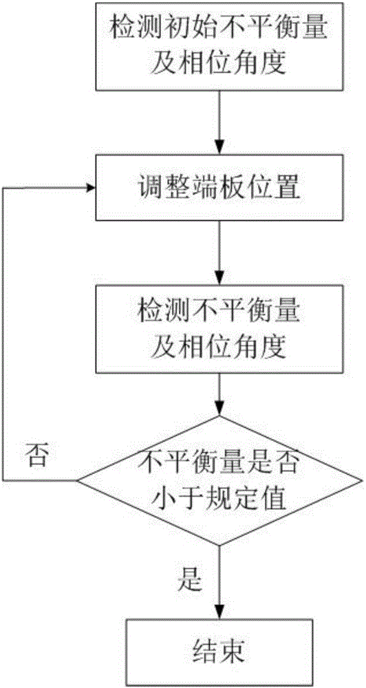
[0025] The concrete implementation method of the present invention is as follows:

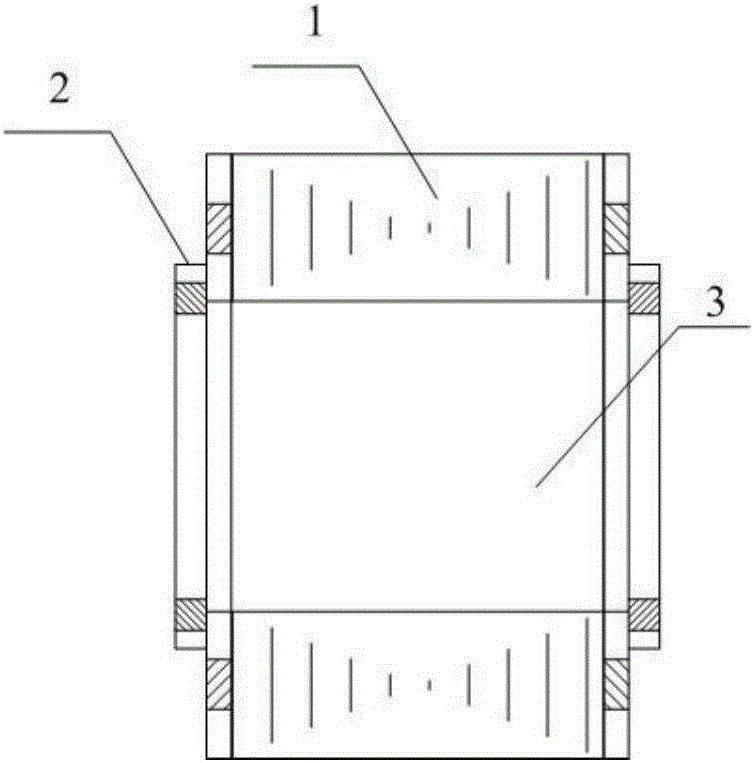
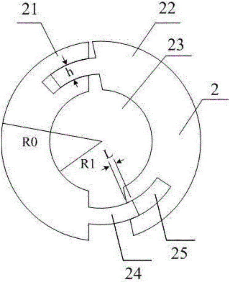
[0026] The existing motor dynamic balance adjustment generally uses a number of round holes on the motor end plate to add lead or copper blocks when using the weight method to adjust the unbalanced amount, and solidify it with balance cement. Although this can also realize the dynamic balance of the motor rotor. Balanced, but due to the limited number of round holes, it is impossible to completely cover the surface of the end plate, which leads to unbalanced phase angles during dynamic balance adjustment. Weighting approximates the dynamic balance, and there is another disadvantage of achieving dynamic balance through the weighting method, that is, due to the high centrifugal force when the high-speed motor is working, the balance weight added through the weighting method may fall off under the action of centrifugal force.

[0027] In order to solve the above problems, the present invention pro...


PUM


Abstract

The invention discloses a novel self-adaptive dynamic balance structure of a motor and an adjusting method thereof. A motor end panel is designed to have a first part and a second part; and the first part and the second part are spliced and can rotate relatively. On the basis of adjustment of positions of the first part and the second part, a dynamic unbalance value is reduced, so that the motor weight is not increased and the danger of shedding of a weighting block on a high-speed condition can be eliminated.

Description

technical field [0001] The invention relates to an electric motor dynamic balance adjustment structure and method, in particular to an electric motor dynamic balance self-adaptive adjustment structure and method. Background technique [0002] The current permanent magnet brushless motor rotor structure includes a shaft, a rotor core, a permanent magnet, and non-magnetic end plates placed at both ends of the rotor (such as aluminum end plates, copper end plates, austenitic stainless steel end plates, etc.), and its production process The sequence is usually as follows: the punching sheets are stacked to form a rotor core, and the rotor core is loaded into the shaft through the temperature difference method or a press machine, and the end close to the shaft shoulder must be placed in a non-magnetic end plate in advance, and the magnetic steel is loaded into the rotor core. Install the non-magnetic end plate at the other end into the magnetic steel slot. Due to the dimensional...

Claims


Application Information

Patent Timeline
Patent Type & Authority Applications(China)
IPC IPC(8): H02K7/04H02K1/22
CPCH02K7/04H02K1/22
Inventor 余国权
Owner TIANJIN SANTROLL ELECTRIC AUTOMOBILE TECH CO LTD
Features
  • R&D
  • Intellectual Property
  • Life Sciences
  • Materials
  • Tech Scout
  • Unparalleled Data Quality
  • Higher Quality Content
  • 60% Fewer Hallucinations
Learn More