
Insulated box, ice box and insulated box assembly used in conjunction with it

A technology for insulated boxes and ice boxes, which is applied in the direction of insulated containers, external accessories, bottle/can parts, etc., which can solve problems such as irregular use of refrigerant, uneven distribution of cold air, and substandard temperature control time, so as to avoid Local overcooling or overheating problems, avoiding the deterioration of consignments, and the effect of appropriate temperature control time

Active Publication Date: 2018-12-21
SF EXPRESS
View PDF6 Cites 0 Cited by
  • Summary
  • Abstract
  • Description
  • Claims
  • Application Information

AI Technical Summary

Problems solved by technology

[0003] However, there is no fixed position for the refrigerant in the incubators currently on the market, resulting in a mixed state of the refrigerant and the product
On the one hand, this structure may cause the refrigerant to squeeze ice cream and other substances that need to be refrigerated and cause damage; on the other hand, the refrigerant in the mixed state may also cause uneven distribution of cold air in the box, resulting in local overcooling or overheating. Deteriorate and damage the consignment
[0004] In addition, since there is no fixed position of refrigerant in the incubator, there are still irregularities in the amount of refrigerant used, resulting in the substandard temperature control time, which also causes the problem of deterioration of materials that need to be refrigerated during transportation.

Method used


Image

  • Insulated box, ice box and insulated box assembly used in conjunction with it
  • Insulated box, ice box and insulated box assembly used in conjunction with it
  • Insulated box, ice box and insulated box assembly used in conjunction with it

Examples


Embodiment 1

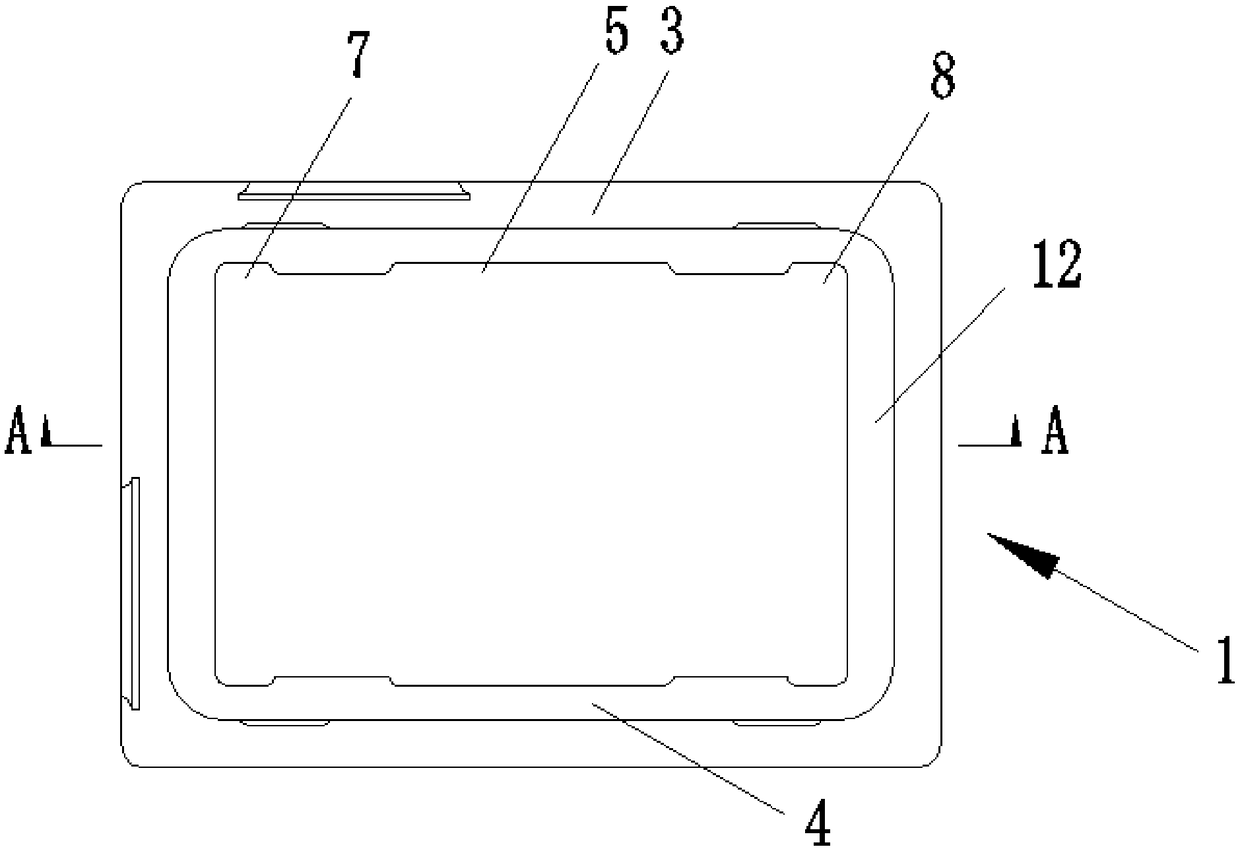
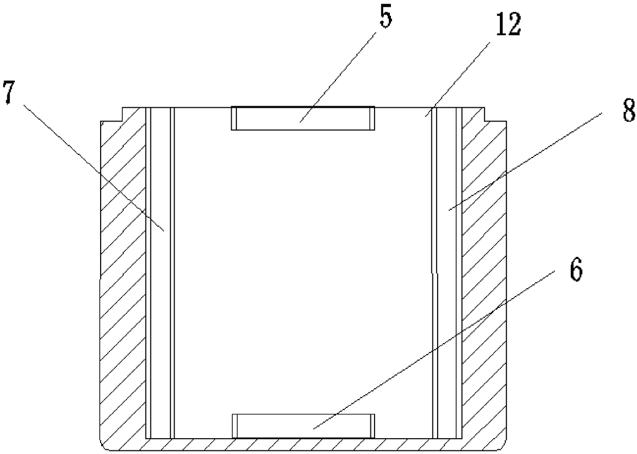
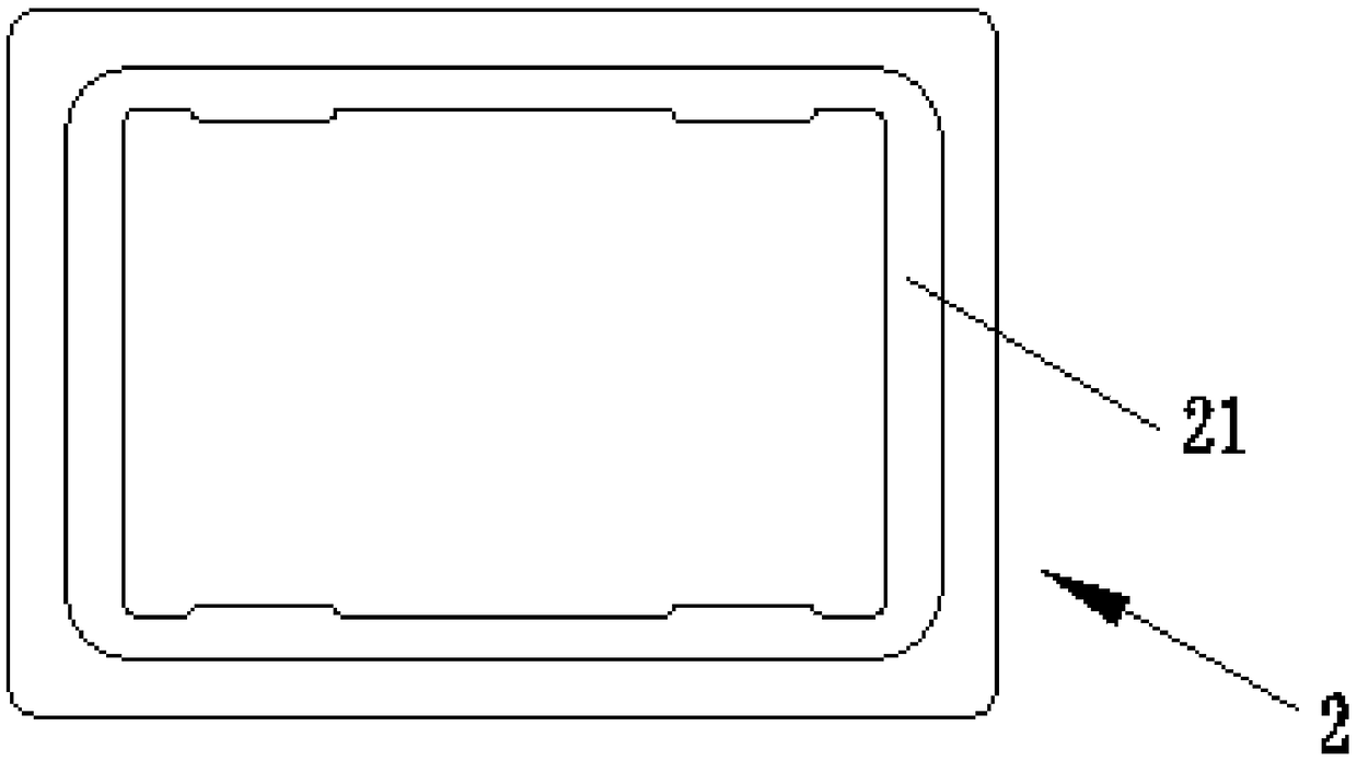
[0047] refer to Figure 1 to Figure 3 , the present embodiment provides an incubator, the incubator includes a box body 1 and a box cover 2 matched with the box body 1;

[0048] The inner surfaces of a pair of parallel side walls 3 and 4 of the box are respectively provided with fixing structures for ice boxes;

[0049] Moreover, the ice boxes located on the inner surfaces of the box body 1 can be jointly fixed by the ice box fixing structure.

[0050] Compared with the prior art, the above-mentioned insulated box is adopted, since the ice box fixing structure is provided to fix the ice boxes located on each inner surface of the box body, so the ice box will not cause damage to the consignment of the box body 1. Squeeze, and the ice box can be reasonably arranged in the box through the fixed structure of the ice box, so that the cold air in the box 1 is evenly distributed, avoiding local overcooling or overheating problems, thereby avoiding deterioration and damage to the con...

Embodiment 2

[0069] see Figure 5 , the present embodiment provides an ice box 15 used in conjunction with the incubator in Example 1. The ice box 15 is a flat rectangular parallelepiped structure, which includes a pair of parallel larger faces and a pair of larger faces located on the pair of larger Two pairs of parallel sides between the faces, one pair is the first side and the other pair is the second side;

[0070] One of the larger surfaces is provided with a positive boss 151;

[0071] One pair of first side surfaces are respectively provided with side bosses 152a, 152b protruding to both sides, and the shape of the side bosses 152a, 152b can be compatible with the first transverse groove 5, the second transverse groove 6, The first vertical groove 7 and the second vertical groove 8 are fitted together.

[0072] The "larger surface" refers to the surface perpendicular to the thickness direction of the ice box 15, and its area is larger than the side area, so it is called "larger s...

Embodiment 3

[0079] see Figure 6 to Figure 12 , the present embodiment provides an incubator assembly, comprising an incubator and ice boxes 15a, 15b, 15c, 15d, 15e, 15f arranged therein, the ice boxes 15a, 15b, 15c, 15d, 15e, 15f It is the ice box 15 described in Embodiment 2;

[0080] The ice boxes 15a, 15b, 15c, 15d, 15e, 15f are fixed in the box body 1 by the ice box fixing structure.

[0081] The ice box is provided on the six inner surfaces inside the box, the ice box 15a on the bottom surface is not provided with the larger side of the positive boss 151, and the larger side of the ice box is set downwards, and the two sides of the ice box are convex. The platforms 152a, 152b are respectively fitted with the second transverse grooves 6 on the adjacent side walls;

[0082] The ice boxes 15b, 15c on the inner surfaces of the pair of parallel side walls are not provided with the side bosses 152a, 152b and are arranged on the outside of the bottom ice box 15a downwards, and are arrang...


PUM


Abstract

The invention provides a heat preservation cabinet and ice boxes used in conjunction with the heat preservation cabinet as well as a heat preservation cabinet assembly. The heat preservation cabinet comprises a cabinet body and a cabinet cover matched with the cabinet body, wherein ice box fixing structures are arranged on the inner surfaces of one pair of parallel side walls of the cabinet body and can be used for jointly fixing the ice boxes located on the inner surfaces of the cabinet body. Compared with the prior art, the heat preservation cabinet provided by the invention has the advantages that the ice boxes do not squeeze deposited goods in the cabinet body; the ice boxes are reasonably arranged in the cabinet body through the ice box fixing structures, so that cold air in the cabinet body is uniformly distributed, and the local supercooling or local superheating problem is avoided, thereby preventing the deposited goods from going bad and being damaged; in addition, as the heat preservation cabinet is internally provided with refrigerant fixing positions, the consumption of refrigerants is standard, the duration of temperature control is appropriate, and the problem in the prior art that the deposited goods go bad, which is caused by substandard temperature control duration, is further avoided.

Description

technical field [0001] The invention relates to an incubator, in particular to an incubator, an ice box and an incubator assembly used in conjunction with the incubator. Background technique [0002] With the rapid rise of the Internet economy and e-commerce, cold chain logistics has become an important development sector of the logistics industry. In terms of mainline cold chain logistics, its operation network has been rapidly supplemented with the growth of market demand. The consumption of refrigerated food such as ice cream is increasing year by year, but in terms of terminal delivery, it is still impossible to effectively realize the whole process of cold transportation of fresh products, resulting in the common phenomenon of thawing or cooling, which in turn affects the quality of ice cream. Therefore, it has become an urgent problem for the industry to develop effective cold chain packaging to solve the delivery of the last mile of the whole cold chain. [0003] How...

Claims


Application Information

Patent Timeline
Patent Type & Authority Patents(China)
IPC IPC(8): B65D81/18B65D81/24B65D81/38B65D43/06B65D25/20
CPCB65D25/205B65D43/06B65D81/18B65D81/24B65D81/3813B65D2543/00194
Inventor 路鹏陈小龙李佳俊曲良献
Owner SF EXPRESS
Learn More